Introduction to devicetree
This page provides an introduction to Devicetree and how it is used in Zephyr.
The following figure shows how devicetree is used by Zephyr’s build system:
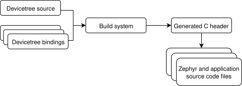
Devicetree build flow
The build system generates a C header file which contains preprocessor
macros with devicetree data. These macros can be referenced
by device drivers and other C code by including
<devicetree.h>. All macro identifiers that are directly generated by
the devicetree scripts start with DT_.
Sometimes, information from devicetree is available using CONFIG_ macros
generated from Kconfig. This happens when devicetree-related
information is referenced from Kconfig symbol definitions via Kconfig
functions. See Devicetree versus Kconfig for some additional
comparisons with Kconfig.
This differs significantly from how devicetree is used on Linux. The Linux kernel would instead read the entire devicetree data structure in its binary form, parsing it at runtime in order to load and initialize device drivers. Zephyr does not work this way because the size of the devicetree binary and associated handling code would be too large to fit comfortably on the relatively constrained devices Zephyr supports.
Syntax and structure
As the name indicates, a devicetree is a tree. The human-readable text format for this tree is called DTS (for devicetree source), and is defined in the Devicetree specification.
Here is an example DTS file:
/dts-v1/;

/ {
        a-node {
                subnode_label: a-sub-node {
                        foo = <3>;
                };
        };
};
The /dts-v1/; line means the file’s contents are in version 1 of the DTS
syntax, which has replaced a now-obsolete “version 0”.
The tree has three nodes:
A root node:
/A node named
a-node, which is a child of the root nodeA node named
a-sub-node, which is a child ofa-node
Nodes can be given labels, which are unique shorthands that can be used to
refer to the labeled node elsewhere in the devicetree. Above, a-sub-node
has label subnode_label.
Devicetree nodes have paths identifying their locations in the tree. Like
Unix file system paths, devicetree paths are strings separated by slashes
(/), and the root node’s path is a single slash: /. Otherwise, each
node’s path is formed by concatenating the node’s ancestors’ names with the
node’s own name, separated by slashes. For example, the full path to
a-sub-node is /a-node/a-sub-node.
Devicetree nodes can also have properties. Properties are name/value
pairs. The values are simple byte arrays. Node a-sub-node has a property
named foo, whose value is a 32-bit big-endian unsigned integer with value
3. The size and type of foo’s value are implied by the enclosing angle
brackets (< and >) in the DTS. Refer to the Devicetree Specification
for a complete list of ways to write a property value in a DTS file.
In practice, devicetree nodes correspond to some hardware, and the node hierarchy reflects the hardware’s physical layout. For example, let’s consider a board with three I2C peripherals connected to an I2C bus controller on an SoC, like this:
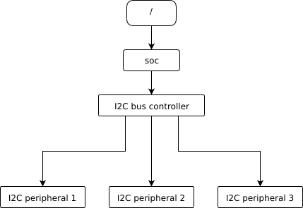
Nodes corresponding to the I2C bus controller and each I2C peripheral would be present in this board’s devicetree. Reflecting the hardware layout, the devicetree’s peripheral nodes would be children of the bus controller node. Similar conventions exist for representing other types of hardware in devicetree.
The DTS would look something like this:
/dts-v1/;

/ {
        soc {
                i2c-bus-controller {
                        i2c-peripheral-1 {
                        };
                        i2c-peripheral-2 {
                        };
                        i2c-peripheral-3 {
                        };
                };
        };
};
Properties are used in practice to describe or configure the hardware the node represents. For example, an I2C peripheral’s node has a property whose value is the peripheral’s address on the bus.
Here’s a tree representing the same example, but with real-world node names and properties you might see when working with I2C devices.
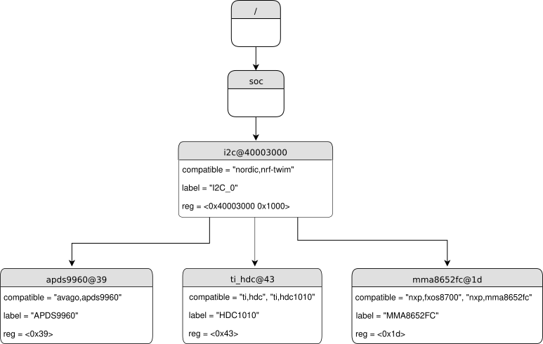
I2C devicetree example with real-world names and properties. Node names are at the top of each node with a gray background. Properties are shown as “name=value” lines.
This is the corresponding DTS:
/dts-v1/;

/ {
        soc {
                i2c@40003000 {
                        compatible = "nordic,nrf-twim";
                        label = "I2C_0";
                        reg = <0x40003000 0x1000>;

                        apds9960@39 {
                                compatible = "avago,apds9960";
                                label = "APDS9960";
                                reg = <0x39>;
                        };
                        ti_hdc@43 {
                                compatible = "ti,hdc", "ti,hdc1010";
                                label = "HDC1010";
                                reg = <0x43>;
                        };
                        mma8652fc@1d {
                                compatible = "nxp,fxos8700", "nxp,mma8652fc";
                                label = "MMA8652FC";
                                reg = <0x1d>;
                        };
                };
        };
};
In addition to showing more realistic names and properties, the above example
introduces a new devicetree concept: unit addresses. Unit addresses are the
parts of node names after an “at” sign (@), like 40003000 in
i2c@40003000, or 39 in apds9960@39. Unit addresses are optional:
the soc node does not have one.
Some more details about unit addresses and important properties follow.
Unit address examples
In devicetree, unit addresses give a node’s address in the address space of its parent node. Here are some example unit addresses for different types of hardware.
- Memory-mapped peripherals
The peripheral’s register map base address. For example, the node named
i2c@40003000represents an I2C controller whose register map base address is 0x40003000.- I2C peripherals
The peripheral’s address on the I2C bus. For example, the child node
apds9960@39of the I2C controller in the previous section has I2C address 0x39.- SPI peripherals
An index representing the peripheral’s chip select line number. (If there is no chip select line, 0 is used.)
- Memory
The physical start address. For example, a node named
memory@2000000represents RAM starting at physical address 0x2000000.- Memory-mapped flash
Like RAM, the physical start address. For example, a node named
flash@8000000represents a flash device whose physical start address is 0x8000000.- Flash partitions
The start offset of the partition within its flash device. For example, take this flash device and its partitions:
flash@8000000 {
    /* ... */
    partitions {
            partition@0 { /* ... */ };
            partition@20000 {  /* ... */ };
            /* ... */
    };
};
The node named
partition@0has offset 0 from the start of its flash device, so its base address is 0x8000000. Similarly, the base address of the node namedpartition@20000is 0x8020000.
Important properties
Some important properties are:
- compatible
Says what kind of device the node represents. The recommended format is
"manufacturer,device", like"avago,apds9960", or a sequence of these, like"ti,hdc", "ti,hdc1010". The file dts/bindings/vendor-prefixes.txt contains a list of acceptedmanufacturerprefixes.It is also sometimes a value like
gpio-keys,mmio-sram, orfixed-clockwhen the hardware’s behavior is generic.The build system uses the compatible property to find the right bindings for the node.
- label
The device’s name according to Zephyr’s Device Driver Model. The value can be passed to
device_get_binding()to retrieve the corresponding driver-level struct device*. This pointer can then be passed to the correct driver API by application code to interact with the device. For example, callingdevice_get_binding("I2C_0")would return a pointer to a device structure which could be passed to I2C API functions likei2c_transfer(). The generated C header will also contain a macro which expands to this string.- reg
Information used to address the device. This could be a memory-mapped I/O address range (as with
i2c@40003000’s reg property), an I2C bus address (as withapds9960@39and its devicetree siblings), a SPI chip select line, or some other value depending on the kind of device the node represents.Unlike a node’s unit address, which is a simple number, the reg property is an array of 32-bit unsigned integers. This is often used to describe the size of a register map. In the case of the
i2c@40003000node above,reg = <0x40003000 0x1000>;means the register map occupies 0x1000 bytes in the memory map.
Input and output files
This section describes the input and output files shown in the figure at the top of this introduction in more detail.

Devicetree input (green) and output (yellow) files
There are four “types” of devicetree files:
sources (
.dts)includes (
.dtsi)overlays (
.overlay)bindings (
.yaml)
The devicetree files inside the zephyr directory look like this:
boards/<ARCH>/<BOARD>/<BOARD>.dts
dts/common/skeleton.dtsi
dts/<ARCH>/.../<SOC>.dtsi
dts/bindings/.../binding.yaml
Generally speaking, every supported board has a BOARD.dts file
describing its hardware. For example, the reel_board has
boards/arm/reel_board/reel_board.dts.
BOARD.dts includes one or more .dtsi files. These .dtsi files
describe the CPU or system-on-chip Zephyr runs on, perhaps by including other
.dtsi files. They can also describe other common hardware features shared by
multiple boards. In addition to these includes, BOARD.dts also describes
the board’s specific hardware.
The dts/common directory contains skeleton.dtsi, a minimal
include file for defining a complete devicetree. Architecture-specific
subdirectories (dts/<ARCH>) contain .dtsi files for CPUs or SoCs
which extend skeleton.dtsi.
The C preprocessor is run on all devicetree files to expand macro references,
and includes are generally done with #include <filename> directives, even
though DTS has a /include/ "<filename>" syntax.
BOARD.dts can be extended or modified using overlays. Overlays are
also DTS files; the .overlay extension is just a convention which makes
their purpose clear. Overlays adapt the base devicetree for different purposes:
Zephyr applications can use overlays to enable a peripheral that is disabled by default, select a sensor on the board for an application specific purpose, etc. Along with Kconfig, this makes it possible to reconfigure the kernel and device drivers without modifying source code.
Overlays are also used when defining Shields.
The build system automatically picks up .overlay files stored in
certain locations. It is also possible to explicitly list the overlays to
include, via the DTC_OVERLAY_FILE CMake variable. See
Devicetree Overlays and Important Build System Variables for details.
The build system combines BOARD.dts and any .overlay files by
concatenating them, with the overlays put last. This relies on DTS syntax which
allows merging overlapping definitions of nodes in the devicetree. See
Example: FRDM-K64F and Hexiwear K64 for an example of how this works (in the context of
.dtsi files, but the principle is the same for overlays). Putting the
contents of the .overlay files last allows them to override
BOARD.dts.
Devicetree bindings (which are YAML files) are essentially glue. They describe
the contents of devicetree sources, includes, and overlays in a way that allows
the build system to generate C macros usable by device drivers and
applications. The dts/bindings directory contains bindings.
These files in the build directory can be useful as a debugging aid when working with devicetree:
- build/zephyr/<BOARD>.dts.pre.tmp
The preprocessed and concatenated DTS sources
- build/zephyr/zephyr.dts
The final merged devicetree. This file is specifically output as a debugging aid, and is unused otherwise.
The following libraries and scripts, located in scripts/dts/, are used to generate C headers from the devicetree and its bindings. Note that the source code has extensive comments and documentation.
- dtlib.py
A low-level DTS parsing library.
- edtlib.py
A library layered on top of dtlib that uses bindings to interpret properties and give a higher-level view of the devicetree. Uses dtlib to do the DTS parsing.
- gen_defines.py
A script that uses edtlib to generate C preprocessor macros from the devicetree and bindings.
The output from gen_defines.py is stored in the build directory as
build/zephyr/include/generated/devicetree_unfixed.h.
In addition to the Python code above, the standard dtc (devicetree
compiler) tool is also run on the final devicetree if it is installed on your
system. This is just to catch any errors or warnings it generates. The output
is unused. Boards may need to pass dtc additional flags, e.g. for warning
suppression. Board directories can contain a file named
pre_dt_board.cmake which configures these extra flags, like this:
list(APPEND EXTRA_DTC_FLAGS "-Wno-simple_bus_reg")
Zephyr currently uses dts_fixup.h files to rename macros in
devicetree_unfixed.h to names that are currently in use by C code. The
build system looks for fixup files in the zephyr/boards/ and
zephyr/soc/ directories by default. Any dts_fixup.h files are
concatenated and stored in the build directory as
build/zephyr/include/generated/devicetree_fixups.h.
Fixup files exist for historical reasons. New code should generally avoid them.
To reference macros generated by gen_defines.py from C, include
devicetree.h. This file is include/devicetree.h in the
zephyr repository; it is not a generated file. It includes the generated
include/devicetree_unfixed.h and include/devicetree_fixups.h
files.
Warning
Do not include the generated C headers from the build directory directly.
Use devicetree.h instead.