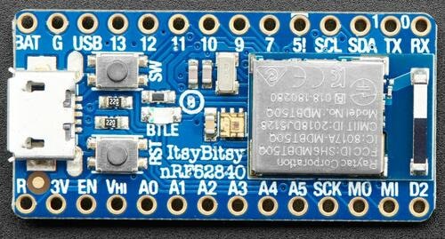
Adafruit ItsyBitsy nRF52840
Overview
The Adafruit ItsyBitsy nRF52840 Express is a small (36 mm x 18 mm) ARM development board with an onboard RGB LED, USB port, 2 MB of QSPI flash, and range of I/O broken out onto 21 GPIO pins.
This development kit has the following features:
ADC
CLOCK
FLASH
GPIO
I2C
I2S
MPU
NVIC
PWM
QSPI
RADIO (Bluetooth Low Energy and 802.15.4)
RTC
SPI
UARTE
USB
WDT

Hardware
nRF52840 ARM Cortex-M4F CPU at 64MHz
1 MB of flash memory and 256 KB of SRAM
2 MB of QSPI flash
A user LED
A user switch
An RGB DotStar LED
Native USB port
One reset button
Supported Features
The Adafruit ItsyBitsy nRF52840 board configuration supports the following hardware features:
Interface |
Controller |
Driver/Component |
|---|---|---|
ADC |
on-chip |
adc |
CLOCK |
on-chip |
clock_control |
FLASH |
on-chip |
flash |
GPIO |
on-chip |
gpio |
I2C |
on-chip |
i2c |
MPU |
on-chip |
arch/arm |
NVIC |
on-chip |
arch/arm |
PWM |
on-chip |
pwm |
QSPI(M) |
on-chip |
nor |
RADIO |
on-chip |
Bluetooth, ieee802154 |
RTC |
on-chip |
system clock |
SPI |
on-chip |
spi |
UARTE |
on-chip |
serial |
USB |
on-chip |
usb |
WDT |
on-chip |
watchdog |
Other hardware features have not been enabled yet for this board.
Connections and IOs
The Adafruit ItsyBitsy nRF52840 Express Learn site [1] has detailed information about the board including pinouts [2] and the schematic [3].
LED
LED0 (red) = P0.06
LED1 (Adafruit DotStar)
DATA = P0.08
CLK = P1.09
Logging
Logging is done using the USB-CDC port. See the Logging sample or the Console over USB CDC ACM sample applications to see how this works.
Programming and Debugging
The ItsyBitsy ships with the BOSSA compatible UF2 bootloader. The bootloader can be entered by quickly tapping the reset button twice.
First time setup
Some versions of this board were shipped with a buggy bootloader. Ensure that the bootloader is up to date by following the Adafruit UF2 Bootloader update [4] tutorial. Note that this tutorial was made for the Adafruit Feather nRF52840, but the steps to update the bootloader are the same for the ItsyBitsy. The files for the ItsyBitsy bootloader can be found in the Adafruit nRF52 Bootloader repo [5].
The building and flashing of Zephyr applications have been tested with release 0.7.0 of the UF2 bootloader.
Flashing
Flashing is done by dragging and dropping the built Zephyr UF2-file
into the ITSY840BOOT drive.
Build the Zephyr kernel and the Blinky sample application:
west build -b adafruit_itsybitsy/nrf52840 samples/basic/blinky
Connect the ItsyBitsy to your host computer using USB
Tap the reset button twice quickly to enter bootloader mode
Flash the image:
Drag and drop the file
samples/basic/blinky/build/zephyr/zephyr.uf2intoITSY840BOOT
The device will disconnect and you should see the red LED blink.