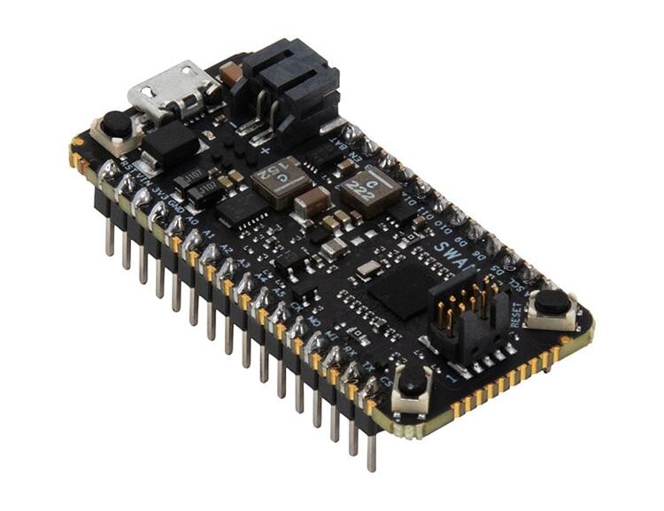
Blues Wireless Swan
Overview
Swan is a low-cost embeddable STM32L4-based microcontroller designed to accelerate the development and deployment of battery-powered solutions. It is especially useful for applications requiring large memory or a high degree of I/O expandability at an affordable cost, such as edge inferencing and remote monitoring.
Uniquely for Feather-compatible boards, Swan is designed to satisfy developers’ needs that span from early prototyping through high-volume deployment. Developers may begin to use Swan in conjunction with Adafruit’s myriad sensors and FeatherWing-compatible carriers. Due to its novel design, for high-volume deployment the low-cost Swan can also be soldered directly to a parent PCB integrating those sensors, utilizing the full range of Swan’s I/O capabilities.
The board has three independent power options-USB, Battery, or Line power- and provides a software-switchable 2 Amp regulator for powering external sensors. When operating in its low-power operating mode, the entire Swan board commonly draws only about 8uA while retaining all of its memory, making it quite suitable for battery-powered devices.
The Swan board features an ARM Cortex-M4 based STM32L4R5ZI MCU with a wide range of connectivity support and configurations. Here are some highlights of the board:
STM32 microcontroller in WLCSP144 package
2MB of flash and 640KB of RAM
Two types of extension resources:
Adafruit Feather-compatible connectivity
Access to 36 additional STM32 pins (beyond the Feather pins) via 0.05” castellated edge headers
On-board ST-LINKV3 debugger/programmer with SWD connector
One Red User LED (LD1)
Two push-buttons: USER and RESET
Castellated-edge access to 55 GPIO ports including:
8 analog
16 digital
4x I2C, 3x SPI
USB OTG full speed
1x 14-channel DMA
tRNG
12-bit ADC, 2 x 12-bit DAC
low-power RTC, and CRC calculation peripherals

More information about the board can be found at the Swan Product Page.
Hardware
The STM32L4R5ZI SoC provides the following hardware IPs:
Ultra-low-power with FlexPowerControl (down to 130 nA Standby mode and 100 uA/MHz run mode)
Core: ARM® 32-bit Cortex®-M4 CPU with FPU, adaptive real-time accelerator (ART Accelerator) allowing 0-wait-state execution from Flash memory, frequency up to 120 MHz, MPU, 150 DMIPS/1.25 DMIPS/MHz (Dhrystone 2.1), and DSP instructions
Memories
2-Mbyte Flash, 2 banks read-while-write, proprietary code readout protection
640 Kbytes of SRAM including 64 Kbytes with hardware parity check
External memory interface for static memories supporting SRAM, PSRAM, NOR, NAND and FRAM memories
2 x OctoSPI memory interface
True random number generator
CRC calculation unit, 96-bit unique ID
Development support: serial wire debug (SWD), JTAG, Embedded Trace Macrocell (ETM)
More information about Swan can be found here:
Supported Features
The Zephyr Swan board configuration supports the following hardware features:
Interface |
Controller |
Driver/Component |
|---|---|---|
NVIC |
on-chip |
nested vector interrupt controller |
UART |
on-chip |
serial port-polling; serial port-interrupt |
PINMUX |
on-chip |
pinmux |
GPIO |
on-chip |
gpio |
I2C |
on-chip |
i2c |
PWM |
on-chip |
pwm |
SPI |
on-chip |
spi |
USB |
on-chip |
usb |
ADC |
on-chip |
adc |
Other hardware features are not yet supported on this Zephyr port.
The default configuration can be found in the defconfig file: boards/blues/swan_r5/swan_r5_defconfig
Connections and IOs
Default Zephyr Peripheral Mapping:
A0 : PA3
A1 : PA1
A2 : PC3
A3 : PC1
A4 : PC4
A5 : PC5
D4 : PE3
D5 : PE11
D6 : PE9
D9 : PD15
D10 : PA4
D11 : PA7
D12 : PA6
D13 : PA5
UART_1_TX : PA9
UART_1_RX : PA10
UART_2_TX : PA2
UART_2_RX : PD6
UART_3_TX : PB10
UART_3_RX : PB11
LPUART_TX : PG7
LPUART_RX : PG8
I2C_1_SCL : PB6
I2C_1_SDA : PB7
I2C_2_SCL : PF1
I2C_2_SDA : PF0
I2C_3_SCL : PC0
I2C_3_SDA : PC9
SPI_1_NSS : PA4
SPI_1_SCK : PA5
SPI_1_MISO : PA6
SPI_1_MOSI : PA7
SPI_2_NSS : PD0
SPI_2_SCK : PD1
SPI_2_MISO : PB14
SPI_2_MOSI : PB15
SPI_3_NSS : PA15
SPI_3_SCK : PC10
SPI_3_MISO : PC11
SPI_3_MOSI : PC12
PWM_2_CH1 : PA0
USER_PB : PC13
LD1 : PE2
USB DM : PA11
USB DP : PA12
ADC1 : PA1
System Clock
Swan System Clock could be driven by internal or external oscillator, as well as main PLL clock. By default, the System clock is driven by the PLL clock at 80MHz, driven by a 16MHz high speed internal oscillator.
Serial Port
Swan has 4 U(S)ARTs. The Zephyr console output is assigned to LPUART. Default settings are 115200 8N1.
Programming and Debugging
Connect Swan to your host computer using the USB port. Then build and flash an application. Here is an example for the Hello World application.
Run a serial host program to connect with your Swan:
$ minicom -D /dev/ttyACM0
Then build and flash the application.
# From the root of the zephyr repository
west build -b swan_r5 samples/hello_world
west flash
You should see the following message on the console:
Hello World! arm