M5Stack StampS3
Overview
M5Stack StampS3 is an ESP32-based development board from M5Stack. It features the following integrated components:
ESP32-S3FN8 chip (240MHz dual core)
512KB SRAM
384KB ROM
8MB Flash
Wi-Fi
Bluetooth
User-Button
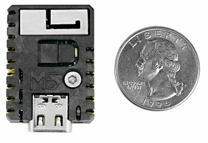
M5Stack StampS3 module
Functional Description
The following table below describes the key components, interfaces, and controls of the M5Stack StampS3 module.
Key Component |
Description |
Status |
|---|---|---|
ESP32-S3FN8 module |
This MPU-ESP32S3 module provides complete Wi-Fi and Bluetooth functionalities and integrates a 8MB flash. |
supported |
Status LED |
One user LED connected via |
supported |
USB Port |
USB interface. Power supply for the board as well as the communication interface between a computer and the board. |
supported |
User button |
User button ( |
supported |
Main connector header
The Zephyr m5stack_stamps3 board can be used on various applications. It
therefore publishes a header definition to be used in different shields:
m5stack,stamps3-header.
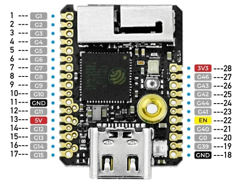
M5Stack StampS3 connector header
Following interfaces are being exported for this header:
m5stack_stamps3_clkout0: PWM output with 2 channels (0 and 2).m5stack_stamps3_spilcd: SPI interface for interfacing LCDs. Consists of a CLK, MOSI and CS signal.m5stack_stamps3_i2c0andm5stack_stamps3_i2c1: I2C interfaces (SDA, SCL).m5stack_stamps3_uart0: UART interface (RXD, TXD).m5stack_stamps3_header: All GPIOs are of course accessible via main header definition.
Pin |
Functions |
Pin |
Functions |
|---|---|---|---|
1 |
|||
2 |
|||
3 |
|
||
4 |
|||
5 |
|
||
6 |
|
||
7 |
|
28 |
3V3 |
8 |
27 |
|
|
9 |
|
26 |
|
10 |
25 |
|
|
11 |
GND |
24 |
|
12 |
|
23 |
|
13 |
5V |
22 |
EN |
14 |
|
21 |
|
15 |
|
20 |
|
16 |
19 |
||
17 |
|
18 |
GND |
Power supply
M5Stack StampS3 requires a single 5V input power supply. The module internally features a DCDC (MUN3CAD01-SC) to generate the 3.3V needed for the MCU.
The EN signal (Pin 22) is an active low signal to enable the 3V3 power supply. If this pin is pulled low this main 3.3V power supply for the MCU will be deactivated. It is internally equipped with a pull-up and can hence be left open if unused.
Start Application Development
Before powering up your M5Stack StampS3, please make sure that the board is in good condition with no obvious signs of damage.
System requirements
Prerequisites
Espressif HAL requires WiFi and Bluetooth binary blobs in order work. Run the command below to retrieve those files.
west blobs fetch hal_espressif
Note
It is recommended running the command above after west update.
Building & Flashing
Build and flash applications as usual (see Building an Application and Run an Application for more details).
# From the root of the zephyr repository
west build -b m5stack_stamps3/esp32s3/procpu samples/hello_world
The usual flash target will work with the m5stack_stamps3 board
configuration. Here is an example for the Hello World
application.
# From the root of the zephyr repository
west build -b m5stack_stamps3/esp32s3/procpu samples/hello_world
west flash
The baud rate of 921600bps is set by default. If experiencing issues when flashing,
try using different values by using --esp-baud-rate <BAUD> option during
west flash (e.g. west flash --esp-baud-rate 115200).
You can also open the serial monitor using the following command:
west espressif monitor
After the board has automatically reset and booted, you should see the following message in the monitor:
***** Booting Zephyr OS vx.x.x-xxx-gxxxxxxxxxxxx *****
Hello World! m5stack_stamps3
Debugging
M5Stack StampS3 exports a JTAG-interface via Pins 19 (MTCK), 21 (MTDO), 23 (MTDI), 25 (MTMS).
Note
Please note that additional JTAG equipment is needed to utilize JTAG. Refer to the ESP32S3 datasheet and the M5Stack StampS3 documentation for details.