NXP MIMXRT1020-EVK
Overview
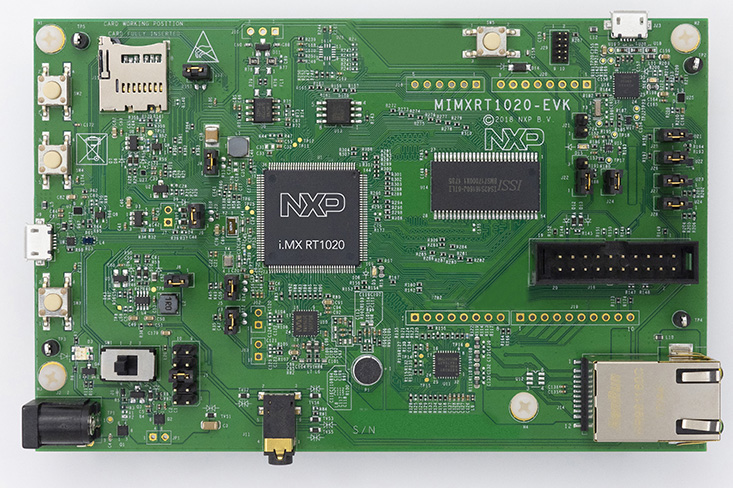
The i.MX RT1020 expands the i.MX RT crossover processor families by providing high-performance feature set in low-cost LQFP packages, further simplifying board design and layout for customers. The i.MX RT1020 runs on the Arm® Cortex®-M7 core at 500 MHz.
Hardware
- MIMXRT1021DAG5A MCU
- Memory
- 256 Mbit SDRAM
- 64 Mbit QSPI Flash
- TF socket for SD card
- Connectivity
- 10/100 Mbit/s Ethernet PHY
- Micro USB host and OTG connectors
- CAN transceivers
- Arduino interface
- Audio
- Audio Codec
- 4-pole audio headphone jack
- Microphone
- External speaker connection
- Power
- 5 V DC jack
- Debug
- JTAG 20-pin connector
- OpenSDA with DAPLink
For more information about the MIMXRT1020 SoC and MIMXRT1020-EVK board, see these references:
- i.MX RT1020 Website
- i.MX RT1020 Datasheet
- i.MX RT1020 Reference Manual
- MIMXRT1020-EVK Website
- MIMXRT1020-EVK User Guide
- MIMXRT1020-EVK Design Files
Supported Features
The mimxrt1020_evk board configuration supports the following hardware features:
| Interface | Controller | Driver/Component |
|---|---|---|
| NVIC | on-chip | nested vector interrupt controller |
| SYSTICK | on-chip | systick |
| GPIO | on-chip | gpio |
| I2C | on-chip | i2c |
| UART | on-chip | serial port-polling; serial port-interrupt |
| ENET | on-chip | ethernet |
The default configuration can be found in the defconfig file:
boards/arm/mimxrt1020_evk/mimxrt1020_evk_defconfig
Other hardware features are not currently supported by the port.
Connections and I/Os
The MIMXRT1020 SoC has five pairs of pinmux/gpio controllers.
| Name | Function | Usage |
|---|---|---|
| GPIO_AD_B0_05 | GPIO | LED |
| GPIO_AD_B0_06 | LPUART1_TX | UART Console |
| GPIO_AD_B0_07 | LPUART1_RX | UART Console |
| GPIO_AD_B1_08 | LPUART2_TX | UART BT HCI |
| GPIO_AD_B1_09 | LPUART2_RX | UART BT HCI |
| GPIO_AD_B1_14 | LPI2C1_SCL | I2C |
| GPIO_AD_B1_15 | LPI2C1_SDA | I2C |
| GPIO_SD_B1_02 | LPI2C4_SCL | I2C |
| GPIO_SD_B1_03 | LPI2C4_SDA | I2C |
| WAKEUP | GPIO | SW0 |
| GPIO_AD_B0_04 | ENET_RST | Ethernet |
| GPIO_AD_B0_08 | ENET_REF_CLK | Ethernet |
| GPIO_AD_B0_09 | ENET_RX_DATA01 | Ethernet |
| GPIO_AD_B0_10 | ENET_RX_DATA00 | Ethernet |
| GPIO_AD_B0_11 | ENET_RX_EN | Ethernet |
| GPIO_AD_B0_12 | ENET_RX_ER | Ethernet |
| GPIO_AD_B0_13 | ENET_TX_EN | Ethernet |
| GPIO_AD_B0_14 | ENET_TX_DATA00 | Ethernet |
| GPIO_AD_B0_15 | ENET_TX_DATA01 | Ethernet |
| GPIO_AD_B1_06 | ENET_INT | Ethernet |
| GPIO_EMC_41 | ENET_MDC | Ethernet |
| GPIO_EMC_40 | ENET_MDIO | Ethernet |
System Clock
The MIMXRT1020 SoC is configured to use the 24 MHz external oscillator on the board with the on-chip PLL to generate a 500 MHz core clock.
Serial Port
The MIMXRT1020 SoC has eight UARTs. LPUART1 is configured for the console,
LPUART2 for the Bluetooth Host Controller Interface (BT HCI), and the
remaining are not used.
Programming and Debugging
Build and flash applications as usual (see Build an Application and Run an Application for more details).
Configuring a Debug Probe
A debug probe is used for both flashing and debugging the board. This board is configured by default to use the OpenSDA DAPLink Onboard Debug Probe, however the pyOCD Debug Host Tools do not yet support programming the external flashes on this board so you must reconfigure the board for one of the following debug probes instead.
Option 1: OpenSDA J-Link Onboard Debug Probe (Recommended)
Install the J-Link Debug Host Tools and make sure they are in your search path.
Follow the instructions in OpenSDA J-Link Onboard Debug Probe to program the OpenSDA J-Link MIMXRT1020-EVK Firmware. Check that jumpers J27 and J28 are on (they are on by default when boards ship from the factory) to ensure SWD signals are connected to the OpenSDA microcontroller.
Option 2: J-Link External Debug Probe
Install the J-Link Debug Host Tools and make sure they are in your search path.
Attach a J-Link 20-pin connector to J16. Check that jumpers J27 and J28 are off (they are on by default when boards ship from the factory) to ensure SWD signals are disconnected from the OpenSDA microcontroller.
Configuring a Console
Regardless of your choice in debug probe, we will use the OpenSDA microcontroller as a usb-to-serial adapter for the serial console. Check that jumpers J25 and J26 are on (they are on by default when boards ship from the factory) to connect UART signals to the OpenSDA microcontroller.
Connect a USB cable from your PC to J23.
Use the following settings with your serial terminal of choice (minicom, putty, etc.):
- Speed: 115200
- Data: 8 bits
- Parity: None
- Stop bits: 1
Flashing
Here is an example for the Hello World application.
# On Linux/macOS
cd $ZEPHYR_BASE/samples/hello_world
mkdir build && cd build

# On Windows
cd %ZEPHYR_BASE%\samples\hello_world
mkdir build & cd build

# Use cmake to configure a Ninja-based build system:
cmake -GNinja -DBOARD=mimxrt1020_evk ..

# Now run ninja on the generated build system:
ninja flash
Open a serial terminal, reset the board (press the SW5 button), and you should see the following message in the terminal:
***** Booting Zephyr OS v1.14.0-rc1 *****
Hello World! mimxrt1020_evk
Debugging
Here is an example for the Hello World application.
# On Linux/macOS
cd $ZEPHYR_BASE/samples/hello_world
mkdir build && cd build

# On Windows
cd %ZEPHYR_BASE%\samples\hello_world
mkdir build & cd build

# Use cmake to configure a Ninja-based build system:
cmake -GNinja -DBOARD=mimxrt1020_evk ..

# Now run ninja on the generated build system:
ninja debug
Open a serial terminal, step through the application in your debugger, and you should see the following message in the terminal:
***** Booting Zephyr OS v1.14.0-rc1 *****
Hello World! mimxrt1020_evk