PSoC63 BLE Pioneer Kit
Overview
The PSoC 6 BLE Pioneer Kit (CY8CKIT-062-BLE) is a hardware platform that enables design and debug of the Cypress PSoC 63 BLE MCU.
The PSoC 6 BLE Pioneer Kit features the PSoC 63 MCU: a dual-core MCU, with a 150-MHz Arm Cortex-M4 as the primary application processor and a 100-MHz Arm Cortex-M0+ that supports low-power operations, 1MB of Flash, 288KB of SRAM, an integrated BLE 4.2 radio, 78 GPIO, 7 programmable analog blocks, 12 programmable digital blocks, and capacitive-sensing with CapSense.
The PSoC 6 BLE Pioneer board offers compatibility with Arduino shields, a 512-Mb NOR flash, onboard programmer/debugger (KitProg2), USB Type-C power delivery system (EZ-PD™ CCG3), 5-segment CapSense slider, two CapSense buttons, one CapSense proximity sensing header, an RGB LED, two user LEDs, and one push button.
The CY8CKIT-062-BLE package includes a CY8CKIT-028-EPD E-INK Display Shield that contains a 2.7-inch E-INK display, a motion sensor, a thermistor, and a PDM microphone. The kit package also contains a CY5677 CySmart BLE 4.2 USB Dongle that is factory-programmed to emulate a BLE GAP Central device, enabling you to emulate a BLE host on your computer.
The Cortex-M0+ is a primary core on the board’s SoC. It starts first and enables the CM4 core.
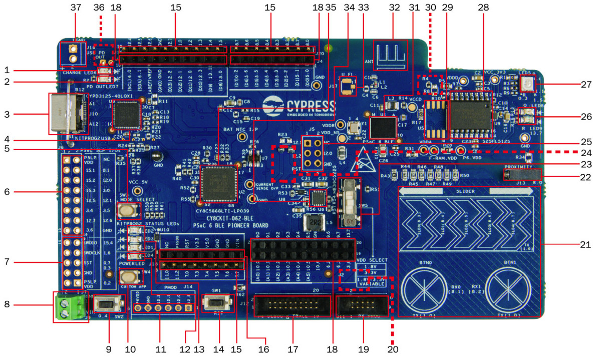
Battery charging indicator (LED6)
USB PD output voltage availability indicator (LED7)
KitProg2 USB Type-C connector (J10)
Cypress EZ-PD™ CCG3 Type-C Port Controller with PD (CYPD3125-40LQXI, U3)
KitProg2 programming mode selection button (SW3)
KitProg2 I/O header (J6)1
KitProg2 programming/custom application header (J7)1
External power supply connector (J9)
PSoC 6 BLE user button (SW2)
KitProg2 application selection button (SW4)
Digilent® Pmod™ compatible I/O header (J14)1
Power LED (LED4)
KitProg2 status LEDs (LED1, LED2, and LED3)
PSoC 6 reset button (SW1)
PSoC 6 I/O header (J18, J19 and J20)
Arduino™ Uno R3 compatible power header (J1)
PSoC 6 debug and trace header (J12)
Arduino Uno R3 compatible PSoC 6 I/O header (J2, J3 and J4)
PSoC 6 program and debug header (J11)
KitProg2 programming target selection switch (SW6)
CapSense slider and buttons
CapSense proximity header (J13)
PSoC 6 BLE VDD selection switch (SW5)
PSoC 6 BLE power monitoring jumper (J8)2
Arduino Uno R3 compatible ICSP header (J5)1
PSoC 6 user LEDs (LED8 and LED9)
RGB LED (LED5)
Cypress 512-Mbit serial NOR Flash memory (S25FL512S, U4)
Cypress serial Ferroelectric RAM (U5)1
VBACKUP and PMIC control selection switch (SW7)2
Cypress PSoC 6 BLE (CY8C6347BZI-BLD53, U1)
BLE Antenna
U.FL connector for external antenna (J17)1
Cypress main voltage regulator (MB39C022G, U6)
KitProg2 (PSoC 5LP) programmer and debugger(CY8C5868LTI-LP039, U2)
Battery connector (J15)1,2
USB PD output voltage (9V/12V) connector (J16)
Hardware
For more information about the PSoC 63 BLE MCU SoC and CY8CKIT-062-BLE board:
Supported Features
The board configuration supports the following hardware features:
Interface |
Controller |
Driver/Component |
|---|---|---|
NVIC |
on-chip |
nested vectored interrupt controller |
SYSTICK |
on-chip |
system clock |
GPIO |
on-chip |
gpio |
UART |
on-chip |
serial port-polling |
The default configurations can be found in the Kconfig boards/arm/cy8ckit_062_ble/cy8ckit_062_ble_m0_defconfig for Cortex-M0+ and on the Kconfig boards/arm/cy8ckit_062_ble/cy8ckit_062_ble_m4_defconfig for Cortex-M4
System Clock
The PSoC 63 BLE MCU SoC is configured to use the internal IMO+FLL as a source for the system clock. CM0+ works at 50MHz, CM4 - at 100MHz. Other sources for the system clock are provided in the SOC, depending on your system requirements.
Serial Port
The PSoC 63 BLE MCU SoC has 8 SCB blocks and each one can be configured as UART/SPI/I2C interfaces for serial communication. At the moment UART5 on SCB5 and UART6 on SCB6 are configured. SCB5 is connected to the onboard KitProg2’s USB-UART Bridge working as a serial console interface. SCB6 to P13_0, P13_1 pins on the J3 of the Arduino Uno R3 compatible PSoC6 I/O header for general purposes.
Programming and Debugging
The CY8CKIT-062-BLE includes an onboard programmer/debugger (KitProg2) with mass storage programming to provide debugging, flash programming, and serial communication over USB. There are also PSoC 6 program and debug headers J11 and J12 that can be used with Segger J-Link [default]. A watchdog timer is enabled by default. To disable it call Cy_WDT_Unlock() and Cy_WDT_Disable().
Build the Zephyr kernel and the Hello World sample application:
west build -b cy8ckit_062_ble_m0 samples/hello_worldRun your favorite terminal program to listen for output. Under Linux the terminal should be
/dev/ttyACM0. For example:$ minicom -D /dev/ttyACM0 -oThe -o option tells minicom not to send the modem initialization string. Connection should be configured as follows:
Speed: 115200
Data: 8 bits
Parity: None
Stop bits: 1
To flash an image:
west build -b cy8ckit_062_ble_m0 samples/hello_world
west flash
You should see “Hello World! cy8ckit_062_ble_m0” in your terminal.