Laird Connectivity Sentrius BT510 Sensor
Overview
The Sentrius™ BT510 Sensor is a battery powered, Bluetooth v5 Long Range integrated sensor that uses a Nordic Semiconductor nRF52840 ARM Cortex-M4F CPU.
The sensor has the following features:
ADC
CLOCK
FLASH
GPIO
I2C
MPU
NVIC
PWM
RADIO (Bluetooth Low Energy and 802.15.4)
RTC
Segger RTT (RTT Console)
UART
WDT
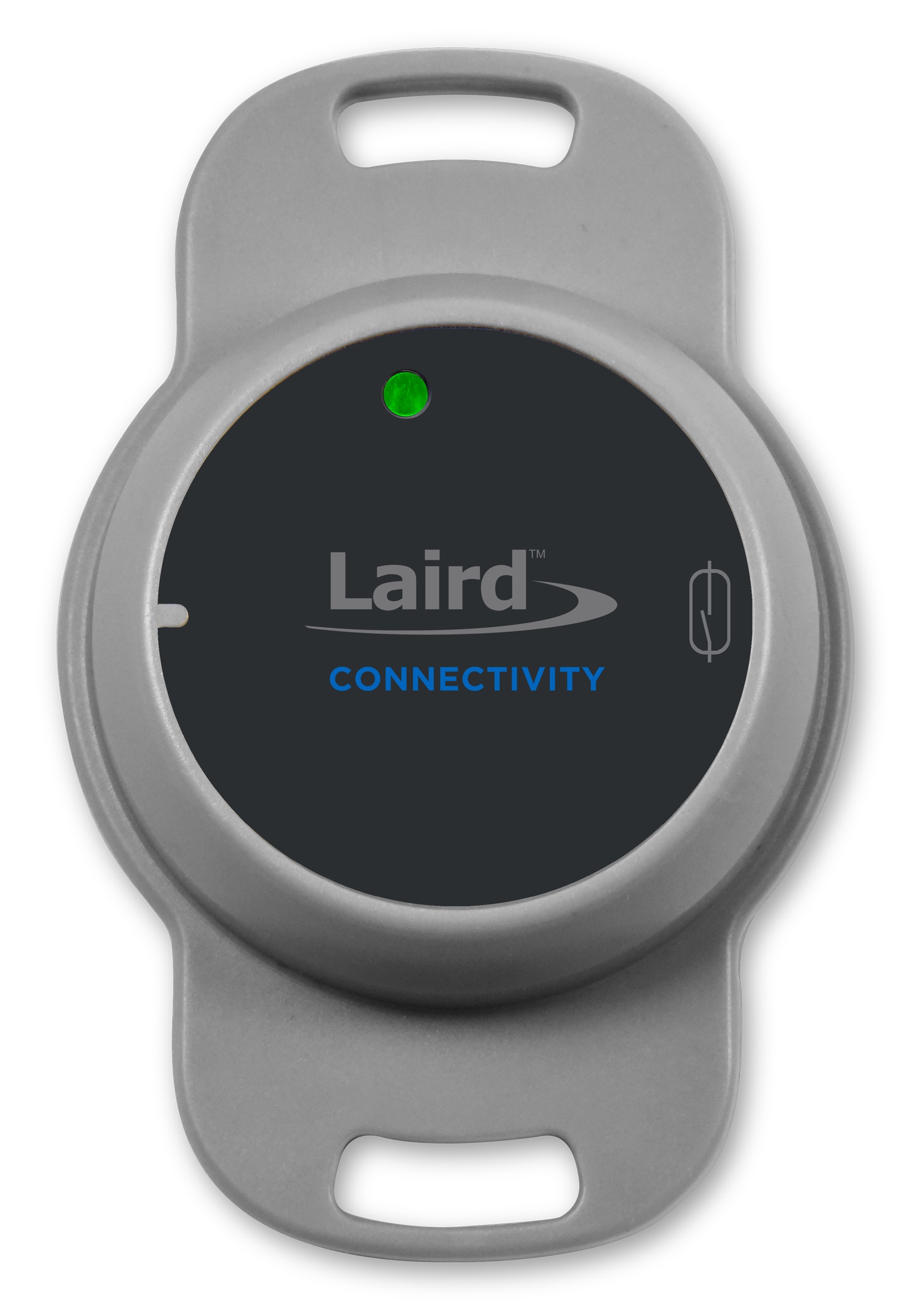
Sentrius BT510 Sensor, front view
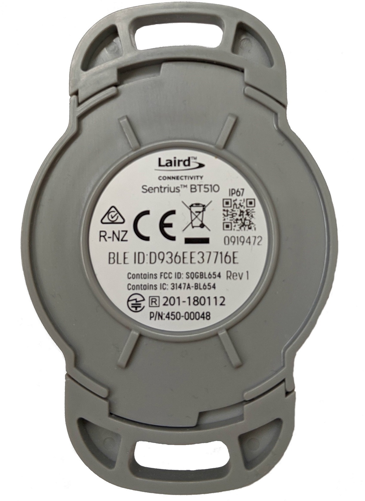
Sentrius BT510 Sensor, rear view
More information about the board can be found at the Sentrius BT510 website 1.
Hardware
Supported Features
The BT510 Sensor supports the following hardware features:
Interface |
Controller |
Driver/Component |
|---|---|---|
ADC |
on-chip |
adc |
CLOCK |
on-chip |
clock_control |
FLASH |
on-chip |
flash |
GPIO |
on-chip |
gpio |
I2C(M) |
on-chip |
i2c |
MPU |
on-chip |
arch/arm |
NVIC |
on-chip |
arch/arm |
PWM |
on-chip |
pwm |
RADIO |
on-chip |
Bluetooth, ieee802154 |
RTC |
on-chip |
system clock |
RTT |
Segger |
console |
UART |
on-chip |
serial |
WDT |
on-chip |
watchdog |
Connections and IOs
LED
Two LEDs are visible through the BT510 housing lid.
LED_1A (green) = P0.22
LED_1B (red) = P0.20
Magnetoresistive sensor
The BT510 incorporates a Honeywell SM351LT magnetoresistive sensor. Refer to the Honeywell SM351LT datasheet 7 for further details.
MAG = P1.14
Accelerometer
The BT510 incorporates an I2C ST Microelectronics LIS2DH accelerometer. Refer to the ST Microelectronics LIS2DH datasheet 6 for further details.
SDA = P0.26
SCL = P0.27
INT_1 = P1.05
INT_2 = P1.12
Temperature Sensor
The BT510 incorporates an I2C Silabs SI7055 temperature sensor. Refer to the Silabs 7055 datasheet 5 for further details.
SDA = P0.26
SCL = P0.27
Programming and Debugging
Applications for the bt510 board configuration can be built, flashed, and
debugged in the usual way. See Building an Application and
Run an Application for more details on building and running.
The BT510 features a TagConnect 10 way socket for connection of a programmer/debugger, refer to TagConnect TC2050 product page 2 for details of an appropriate TagConnect cable.
A non-standard layout is used to include access to the sensor debug UART.
Pin No. |
Name |
Description |
|---|---|---|
1 |
Vcc |
Power Supply, 3.3V |
2 |
SWDIO |
SWD Data |
3 |
RXD |
Debug UART RX Data |
4 |
SWDCLK |
SWD Clock |
5 |
TM |
Spare GPIO |
6 |
SWO |
SWD Output |
7 |
N/C |
Not Connected |
8 |
TXD |
Debug UART TX Data |
9 |
GND |
Ground |
10 |
RESET |
Reset, Active Low |
Connectivity to the programmer/debugger must be modified to match the pinout shown above.
Laird Connectivity provide the USB-SWD programming board that supports this connector layout, refer to the USB SWD Programmer product page 3 .
Flashing
Follow the instructions in the Nordic nRF5x Segger J-Link page to install and configure all the necessary software. Further information can be found in Flashing. Then build and flash applications as usual (see Building an Application and Run an Application for more details).
Here is an example for the Hello World application.
First, run your favorite terminal program to listen for output.
NOTE: On the BT510, the UART lines are at TTL levels and must be passed through an appropriate line driver circuit for translation to RS232 levels. Refer to the MAX3232 datasheet 4 for a suitable driver IC.
$ minicom -D <tty_device> -b 115200
Replace <tty_device> with the port where the bt510 can be found. For example, under Linux, /dev/ttyUSB0.
Then build and flash the application in the usual way.
# From the root of the zephyr repository
west build -b bt510 samples/hello_world
west flash
Note that an external debugger is required to perform application flashing.
Debugging
The bt510 board does not have an on-board J-Link debug IC
as some nRF5x development boards, however, instructions from the
Nordic nRF5x Segger J-Link page also apply to this board, with the additional step
of connecting an external debugger.
Testing Bluetooth on the BT510
Many of the Bluetooth examples will work on the BT510. Try them out:
Testing the LEDs and buttons on the BT510
There are 2 samples that allow you to test that the buttons (switches) and LEDs on the board are working properly with Zephyr:
You can build and flash the examples to make sure Zephyr is running correctly on your board. The button, LED and sensor device definitions can be found in boards/arm/bt510/bt510.dts.