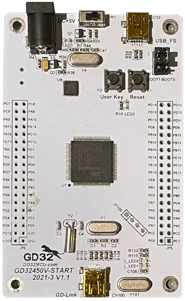
GigaDevice GD32F450V-START
Overview
The GD32F450V-START board is a hardware platform that enables prototyping on GD32F450VK Cortex-M4F Stretch Performance MCU.
The GD32F450VK features a single-core ARM Cortex-M4F MCU which can run up to 200 MHz with flash accesses zero wait states, 3072kiB of Flash, 256kiB of SRAM and 82 GPIOs.

Hardware
GD32F450VKT6 MCU
1 x User LEDs
1 x User Push buttons
USB FS/HS connectors
GD-Link on board programmer
J-Link/SWD connector
For more information about the GD32F450 SoC and GD32F450V-START board:
Supported Features
The board configuration supports the following hardware features:
Peripheral |
Kconfig option |
Devicetree compatible |
|---|---|---|
EXTI |
||
GPIO |
||
NVIC |
N/A |
|
PWM |
||
SYSTICK |
N/A |
N/A |
USART |
Other peripherals may be used if shields are connected to the board.
Serial Port
The GD32F450V-START board has no exposed serial communication port. The board provides default configuration for USART0 with TX connected at PB6 and RX at PB7. PB6/PB7 are exposed in JP6, so you can solder a connector and use a UART-USB adapter.
Programming and Debugging
Before programming your board make sure to configure boot jumpers as follows:
JP2/3: Select 2-3 for both (boot from user memory)
Using GD-Link
The GD32F450V-START includes an onboard programmer/debugger (GD-Link) which allows flash programming and debugging over USB. There is also a SWD header (JP100) which can be used with tools like Segger J-Link.
Build the Zephyr kernel and the Hello World sample application:
west build -b gd32f450v_start samples/hello_world
Run your favorite terminal program to listen for output. On Linux the terminal should be something like
/dev/ttyUSB0. For example:minicom -D /dev/ttyUSB0 -oThe -o option tells minicom not to send the modem initialization string. Connection should be configured as follows:
Speed: 115200
Data: 8 bits
Parity: None
Stop bits: 1
To flash an image:
west build -b gd32f450v_start samples/hello_world
west flash
You should see “Hello World! gd32f450v_start” in your terminal.
To debug an image:
west build -b gd32f450v_start samples/hello_world
west debug