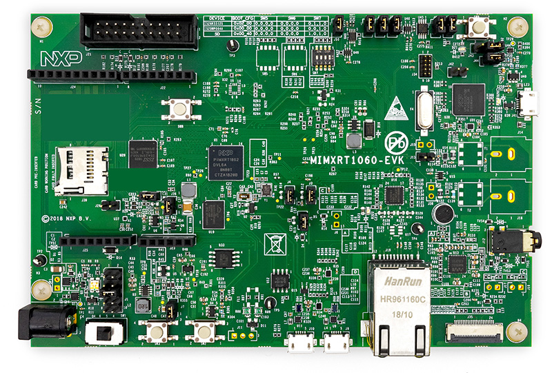
NXP MIMXRT1060-EVK
Overview
The i.MX RT1060 is the latest addition to the industry’s first crossover processor series and expands the i.MX RT series to three scalable families.
The i.MX RT1060 doubles the On-Chip SRAM to 1MB while keeping pin-to-pin compatibility with i.MX RT1050. This new series introduces additional features ideal for real-time applications such as High-Speed GPIO, CAN-FD, and synchronous parallel NAND/NOR/PSRAM controller. The i.MX RT1060 runs on the Arm® Cortex-M7® core at 600 MHz.
Hardware
- MIMXRT1062DVL6A MCU (600 MHz, 1024 KB on-chip memory)
- Memory
- 256 Mbit SDRAM
- 64 Mbit QSPI Flash
- 512 Mbit Hyper Flash
- TF socket for SD card
- Display
- LCD connector
- Ethernet
- 10/100 Mbit/s Ethernet PHY
- USB
- USB 2.0 OTG connector
- USB 2.0 host connector
- Audio
- 3.5 mm audio stereo headphone jack
- Board-mounted microphone
- Left and right speaker out connectors
- Power
- 5 V DC jack
- Debug
- JTAG 20-pin connector
- OpenSDA with DAPLink
- Sensor
- FXOS8700CQ 6-axis e-compass
- CMOS camera sensor interface
- Expansion port
- Arduino interface
- CAN bus connector
For more information about the MIMXRT1060 SoC and MIMXRT1060-EVK board, see these references:
- i.MX RT1060 Website
- i.MX RT1060 Datasheet
- i.MX RT1060 Reference Manual
- MIMXRT1060-EVK Website
- MIMXRT1060-EVK User Guide
- MIMXRT1060-EVK Schematics
Supported Features
The mimxrt1060_evk board configuration supports the following hardware features:
| Interface | Controller | Driver/Component |
|---|---|---|
| NVIC | on-chip | nested vector interrupt controller |
| SYSTICK | on-chip | systick |
| DISPLAY | on-chip | display |
| GPIO | on-chip | gpio |
| UART | on-chip | serial port-polling; serial port-interrupt |
The default configuration can be found in the defconfig file:
boards/arm/mimxrt1060_evk/mimxrt1060_evk_defconfig
Other hardware features are not currently supported by the port.
Connections and I/Os
The MIMXRT1060 SoC has five pairs of pinmux/gpio controllers.
| Name | Function | Usage |
|---|---|---|
| GPIO_AD_B0_02 | LCD_RST | LCD Display |
| GPIO_AD_B0_09 | GPIO | LED |
| GPIO_AD_B0_12 | LPUART1_TX | UART Console |
| GPIO_AD_B0_13 | LPUART1_RX | UART Console |
| GPIO_AD_B1_06 | LPUART3_TX | UART BT HCI |
| GPIO_AD_B1_07 | LPUART3_RX | UART BT HCI |
| WAKEUP | GPIO | SW0 |
| GPIO_B0_00 | LCD_CLK | LCD Display |
| GPIO_B0_01 | LCD_ENABLE | LCD Display |
| GPIO_B0_02 | LCD_HSYNC | LCD Display |
| GPIO_B0_03 | LCD_VSYNC | LCD Display |
| GPIO_B0_04 | LCD_DATA00 | LCD Display |
| GPIO_B0_05 | LCD_DATA01 | LCD Display |
| GPIO_B0_06 | LCD_DATA02 | LCD Display |
| GPIO_B0_07 | LCD_DATA03 | LCD Display |
| GPIO_B0_08 | LCD_DATA04 | LCD Display |
| GPIO_B0_09 | LCD_DATA05 | LCD Display |
| GPIO_B0_10 | LCD_DATA06 | LCD Display |
| GPIO_B0_11 | LCD_DATA07 | LCD Display |
| GPIO_B0_12 | LCD_DATA08 | LCD Display |
| GPIO_B0_13 | LCD_DATA09 | LCD Display |
| GPIO_B0_14 | LCD_DATA10 | LCD Display |
| GPIO_B0_15 | LCD_DATA11 | LCD Display |
| GPIO_B1_00 | LCD_DATA12 | LCD Display |
| GPIO_B1_01 | LCD_DATA13 | LCD Display |
| GPIO_B1_02 | LCD_DATA14 | LCD Display |
| GPIO_B1_03 | LCD_DATA15 | LCD Display |
| GPIO_B1_15 | BACKLIGHT_CTL | LCD Display |
System Clock
The MIMXRT1060 SoC is configured to use the 24 MHz external oscillator on the board with the on-chip PLL to generate a 600 MHz core clock.
Serial Port
The MIMXRT1060 SoC has eight UARTs. LPUART1 is configured for the console,
LPUART3 for the Bluetooth Host Controller Interface (BT HCI), and the
remaining are not used.
Programming and Debugging
Build and flash applications as usual (see Build an Application and Run an Application for more details).
Configuring a Debug Probe
A debug probe is used for both flashing and debugging the board. This board is configured by default to use the OpenSDA DAPLink Onboard Debug Probe, however the pyOCD Debug Host Tools do not yet support programming the external flashes on this board so you must reconfigure the board for one of the following debug probes instead.
J-Link External Debug Probe
Install the J-Link Debug Host Tools and make sure they are in your search path.
Attach a J-Link 20-pin connector to J21. Check that jumpers J47 and J48 are off (they are on by default when boards ship from the factory) to ensure SWD signals are disconnected from the OpenSDA microcontroller.
Configuring a Console
Regardless of your choice in debug probe, we will use the OpenSDA microcontroller as a usb-to-serial adapter for the serial console. Check that jumpers J45 and J46 are on (they are on by default when boards ship from the factory) to connect UART signals to the OpenSDA microcontroller.
Connect a USB cable from your PC to J41.
Use the following settings with your serial terminal of choice (minicom, putty, etc.):
- Speed: 115200
- Data: 8 bits
- Parity: None
- Stop bits: 1
Flashing
Here is an example for the Hello World application.
# On Linux/macOS
cd $ZEPHYR_BASE/samples/hello_world
mkdir build && cd build

# On Windows
cd %ZEPHYR_BASE%\samples\hello_world
mkdir build & cd build

# Use cmake to configure a Ninja-based build system:
cmake -GNinja -DBOARD=mimxrt1060_evk ..

# Now run ninja on the generated build system:
ninja flash
Open a serial terminal, reset the board (press the SW9 button), and you should see the following message in the terminal:
***** Booting Zephyr OS v1.14.0-rc1 *****
Hello World! mimxrt1060_evk
Debugging
Here is an example for the Hello World application.
# On Linux/macOS
cd $ZEPHYR_BASE/samples/hello_world
mkdir build && cd build

# On Windows
cd %ZEPHYR_BASE%\samples\hello_world
mkdir build & cd build

# Use cmake to configure a Ninja-based build system:
cmake -GNinja -DBOARD=mimxrt1060_evk ..

# Now run ninja on the generated build system:
ninja debug
Open a serial terminal, step through the application in your debugger, and you should see the following message in the terminal:
***** Booting Zephyr OS v1.14.0-rc1 *****
Hello World! mimxrt1060_evk