NXP MIMXRT1050-EVK
Overview
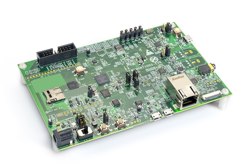
The i.MX RT1050 is a new processor family featuring NXP’s advanced implementation of the ARM Cortex-M7 Core. It provides high CPU performance and real-time response.
The i.MX RT1050 provides various memory interfaces, including SDRAM, Raw NAND FLASH, NOR FLASH, SD/eMMC, Quad SPI, HyperBus and a wide range of other interfaces for connecting peripherals, such as WLAN, Bluetooth™, GPS, displays, and camera sensors. As with other i.MX processors, i.MX RT1050 also has rich audio and video features, including LCD display, basic 2D graphics, camera interface, SPDIF, and I2S audio interface.
The following document refers to the discontinued MIMXRT1050-EVK board. For the MIMXRT1050-EVKB board, refer to Board Revisions section.
Hardware
- MIMXRT1052DVL6A MCU (600 MHz, 512 KB TCM)
- Memory
- 256 KB SDRAM
- 64 Mbit QSPI Flash
- 512 Mbit Hyper Flash
- Display
- LCD connector
- Touch connector
- Ethernet
- 10/100 Mbit/s Ethernet PHY
- USB
- USB 2.0 OTG connector
- USB 2.0 host connector
- Audio
- 3.5 mm audio stereo headphone jack
- Board-mounted microphone
- Left and right speaker out connectors
- Power
- 5 V DC jack
- Debug
- JTAG 20-pin connector
- OpenSDA with DAPLink
- Sensor
- FXOS8700CQ 6-axis e-compass
- CMOS camera sensor interface
- Expansion port
- Arduino interface
- CAN bus connector
For more information about the MIMXRT1050 SoC and MIMXRT1050-EVK board, see these references:
- i.MX RT1050 Website
- i.MX RT1050 Datasheet
- i.MX RT1050 Reference Manual
- MIMXRT1050-EVK Website
- MIMXRT1050-EVK User Guide
- MIMXRT1050-EVK Schematics
Supported Features
The mimxrt1050_evk board configuration supports the following hardware features:
| Interface | Controller | Driver/Component |
|---|---|---|
| NVIC | on-chip | nested vector interrupt controller |
| SYSTICK | on-chip | systick |
| DISPLAY | on-chip | display |
| GPIO | on-chip | gpio |
| I2C | on-chip | i2c |
| SPI | on-chip | spi |
| UART | on-chip | serial port-polling; serial port-interrupt |
| ENET | on-chip | ethernet |
The default configuration can be found in the defconfig file:
boards/arm/mimxrt1050_evk/mimxrt1050_evk_defconfig
Other hardware features are not currently supported by the port.
Connections and IOs
The MIMXRT1050 SoC has five pairs of pinmux/gpio controllers.
| Name | Function | Usage |
|---|---|---|
| GPIO_AD_B0_00 | LPSPI3_SCK | SPI |
| GPIO_AD_B0_01 | LPSPI3_SDO | SPI |
| GPIO_AD_B0_02 | LPSPI3_SDI/LCD_RST| SPI/LCD Display | |
| GPIO_AD_B0_03 | LPSPI3_PCS0 | SPI |
| GPIO_AD_B0_09 | GPIO/ENET_RST | LED |
| GPIO_AD_B0_10 | GPIO/ENET_INT | GPIO/Ethernet |
| GPIO_AD_B0_12 | LPUART1_TX | UART Console |
| GPIO_AD_B0_13 | LPUART1_RX | UART Console |
| GPIO_AD_B1_00 | LPI2C1_SCL | I2C |
| GPIO_AD_B1_01 | LPI2C1_SDA | I2C |
| GPIO_AD_B1_06 | LPUART3_TX | UART BT HCI |
| GPIO_AD_B1_07 | LPUART3_RX | UART BT HCI |
| WAKEUP | GPIO | SW0 |
| GPIO_B0_00 | LCD_CLK | LCD Display |
| GPIO_B0_01 | LCD_ENABLE | LCD Display |
| GPIO_B0_02 | LCD_HSYNC | LCD Display |
| GPIO_B0_03 | LCD_VSYNC | LCD Display |
| GPIO_B0_04 | LCD_DATA00 | LCD Display |
| GPIO_B0_05 | LCD_DATA01 | LCD Display |
| GPIO_B0_06 | LCD_DATA02 | LCD Display |
| GPIO_B0_07 | LCD_DATA03 | LCD Display |
| GPIO_B0_08 | LCD_DATA04 | LCD Display |
| GPIO_B0_09 | LCD_DATA05 | LCD Display |
| GPIO_B0_10 | LCD_DATA06 | LCD Display |
| GPIO_B0_11 | LCD_DATA07 | LCD Display |
| GPIO_B0_12 | LCD_DATA08 | LCD Display |
| GPIO_B0_13 | LCD_DATA09 | LCD Display |
| GPIO_B0_14 | LCD_DATA10 | LCD Display |
| GPIO_B0_15 | LCD_DATA11 | LCD Display |
| GPIO_B1_00 | LCD_DATA12 | LCD Display |
| GPIO_B1_01 | LCD_DATA13 | LCD Display |
| GPIO_B1_02 | LCD_DATA14 | LCD Display |
| GPIO_B1_03 | LCD_DATA15 | LCD Display |
| GPIO_B1_04 | ENET_RX_DATA00 | Ethernet |
| GPIO_B1_05 | ENET_RX_DATA01 | Ethernet |
| GPIO_B1_06 | ENET_RX_EN | Ethernet |
| GPIO_B1_07 | ENET_TX_DATA00 | Ethernet |
| GPIO_B1_08 | ENET_TX_DATA01 | Ethernet |
| GPIO_B1_09 | ENET_TX_EN | Ethernet |
| GPIO_B1_10 | ENET_REF_CLK | Ethernet |
| GPIO_B1_11 | ENET_RX_ER | Ethernet |
| GPIO_B1_15 | BACKLIGHT_CTL | LCD Display |
| GPIO_EMC_40 | ENET_MDC | Ethernet |
| GPIO_EMC_41 | ENET_MDIO | Ethernet |
| GPIO_AD_B0_09 | ENET_RST | Ethernet |
| GPIO_AD_B0_10 | ENET_INT | Ethernet |
System Clock
The MIMXRT1050 SoC is configured to use the 24 MHz external oscillator on the board with the on-chip PLL to generate a 600 MHz core clock.
Serial Port
The MIMXRT1050 SoC has eight UARTs. LPUART1 is configured for the console,
LPUART3 for the Bluetooth Host Controller Interface (BT HCI), and the
remaining are not used.
Programming and Debugging
Build and flash applications as usual (see Build an Application and Run an Application for more details).
Configuring a Debug Probe
A debug probe is used for both flashing and debugging the board. This board is configured by default to use the OpenSDA DAPLink Onboard Debug Probe, however the pyOCD Debug Host Tools do not yet support programming the external flashes on this board so you must reconfigure the board for one of the following debug probes instead.
Option 1: OpenSDA J-Link Onboard Debug Probe (Recommended)
Install the J-Link Debug Host Tools and make sure they are in your search path.
Follow the instructions in OpenSDA J-Link Onboard Debug Probe to program the OpenSDA J-Link MIMXRT1050-EVK-Hyperflash Firmware. Check that jumpers J32 and J33 are on (they are on by default when boards ship from the factory) to ensure SWD signals are connected to the OpenSDA microcontroller.
Option 2: J-Link External Debug Probe
Install the J-Link Debug Host Tools and make sure they are in your search path.
Attach a J-Link 20-pin connector to J21. Check that jumpers J32 and J33 are off (they are on by default when boards ship from the factory) to ensure SWD signals are disconnected from the OpenSDA microcontroller.
Configuring a Console
Regardless of your choice in debug probe, we will use the OpenSDA microcontroller as a usb-to-serial adapter for the serial console. Check that jumpers J30 and J31 are on (they are on by default when boards ship from the factory) to connect UART signals to the OpenSDA microcontroller.
Connect a USB cable from your PC to J28.
Use the following settings with your serial terminal of choice (minicom, putty, etc.):
- Speed: 115200
- Data: 8 bits
- Parity: None
- Stop bits: 1
Flashing
Here is an example for the Hello World application.
# On Linux/macOS
cd $ZEPHYR_BASE/samples/hello_world
mkdir build && cd build

# On Windows
cd %ZEPHYR_BASE%\samples\hello_world
mkdir build & cd build

# Use cmake to configure a Ninja-based build system:
cmake -GNinja -DBOARD=mimxrt1050_evk ..

# Now run ninja on the generated build system:
ninja flash
Open a serial terminal, reset the board (press the SW4 button), and you should see the following message in the terminal:
***** Booting Zephyr OS v1.14.0-rc1 *****
Hello World! mimxrt1050_evk
Debugging
Here is an example for the Hello World application.
# On Linux/macOS
cd $ZEPHYR_BASE/samples/hello_world
mkdir build && cd build

# On Windows
cd %ZEPHYR_BASE%\samples\hello_world
mkdir build & cd build

# Use cmake to configure a Ninja-based build system:
cmake -GNinja -DBOARD=mimxrt1050_evk ..

# Now run ninja on the generated build system:
ninja debug
Open a serial terminal, step through the application in your debugger, and you should see the following message in the terminal:
***** Booting Zephyr OS v1.14.0-rc1 *****
Hello World! mimxrt1050_evk
Board Revisions
The original MIMXRT1050-EVK (rev A0) board was updated with a newer MIMXRT1050-EVKB (rev A1) board, with these major hardware differences:
- SoC changed from MIMXRT1052DVL6**A** to MIMXRT1052DVL6**B**
- Hardware bug fixes for: power, interfaces, and memory
- Arduino headers included
For more details, please see the following NXP i.MXRT1050 A0 to A1 Migration Guide.
Current Zephyr build supports the new MIMXRT1050-EVKB