Particle Boron
Overview
The Particle Boron is a cellular-enabled development board with a Nordic Semiconductor nRF52840 for mesh support and an LTE or 2G/3G modem. The board was developed by Particle Industries and has a SWD connector on it for programming.
It is equipped with a onboard LIPO circuit and conforms to the Adafruit Feather formfactor.
The Particle Boron board provides support for the Nordic Semiconductor nRF52840 ARM® Cortex®-M4F SoC with an integrated 2.4 GHz transceiver supporting Bluetooth® Low Energy and IEEE® 802.15.4.
For more information about the Particle Boron board:
Hardware
On the front of the board are RGB-LED, LED and LIPO circuitry. The RGB-LED is controlled by the nRF52840 via GPIO pins.
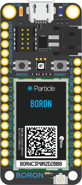
Particle Boron (Credit: Particle Industries)
Power supply
The board is optimized for low power applications and supports two power source configurations: battery and micro USB connector.
It contains circuitry for LIPO usage and can be charged via the USB port.
Supported Features
The particle_boron board configuration supports the following hardware features:
| Interface | Controller | Driver/Component |
|---|---|---|
| NVIC | on-chip | nested vectored interrupt controller |
| RTC | on-chip | system clock |
| UART | on-chip | serial port |
| I2C | on-chip | i2c |
| SPI | on-chip | spi |
| GPIO | on-chip | gpio |
| FLASH | on-chip | flash |
| RADIO | on-chip | Bluetooth |
Other hardware features are not supported by the Zephyr kernel.
Connections and IOs
Please see the Boron Datasheet for header pin assignments, which are common to all Feather-compatible Particle boards. Some peripherals are available to applications through DTS overlay include directives:
mesh_feather_spi_spi3.dtsiexposes SPI3 on labeled Feather SPI pinsmesh_feather_spi1_spi3.dtsiexposes SPI3 on labeled Feather SPI1 pinsmesh_feather_uart1_rtscts.dtsiadds hardware flow control to labeled Feather UART pins
LED
- LED0 (blue)
- LED1 (red)
- LED2 (green)
- LED3 (blue)
Push buttons
- SW0 via MODE
- SW1 via RESET
I2C
- TWI0 enabled on labeled header (SDA/SCL)
- TWI1 enabled for internal power management ICs
SPI
- SPI0 disabled due to TWI0 conflict
- SPI1 disabled due to TWI1 conflict
- SPI2 internal to 32 Mb CFI flash chip
- SPI3 selectable with overlay (SPI or SPI1)
UART
- UARTE0 enabled RX/TX on labeled header (UART1); add RTS/CTS with overlay
- UARTE1 internal to u-blox cellular modem
Programming and Debugging
Applications for the particle_boron board configuration can be
built and flashed in the usual way (see Build an Application
and Run an Application for more details).
Flashing
Build and flash an application in the usual way, for example:
# On Linux/macOS
cd $ZEPHYR_BASE/samples/basic/blinky
mkdir build && cd build

# On Windows
cd %ZEPHYR_BASE%\samples\basic\blinky
mkdir build & cd build

# Use cmake to configure a Ninja-based build system:
cmake -GNinja -DBOARD=particle_boron ..

# Now run ninja on the generated build system:
ninja
ninja flash
Debugging
You can debug an application in the usual way. Here is an example for the Hello World application.
# On Linux/macOS
cd $ZEPHYR_BASE/samples/hello_world
# If you already made a build directory (build) and ran cmake, just 'cd build' instead.
mkdir build && cd build

# On Windows
cd %ZEPHYR_BASE%\samples\hello_world
# If you already made a build directory (build) and ran cmake, just 'cd build' instead.
mkdir build & cd build

# Use cmake to configure a Ninja-based build system:
cmake -GNinja -DBOARD=particle_boron ..

# Now run ninja on the generated build system:
ninja debug
Testing the LEDs and buttons
There are 2 samples that allow you to test that the buttons (switches) and LEDs on the board are working properly with Zephyr:
You can build and flash the examples to make sure Zephyr is running correctly on your board.