NXP FRDM-K64F
Overview
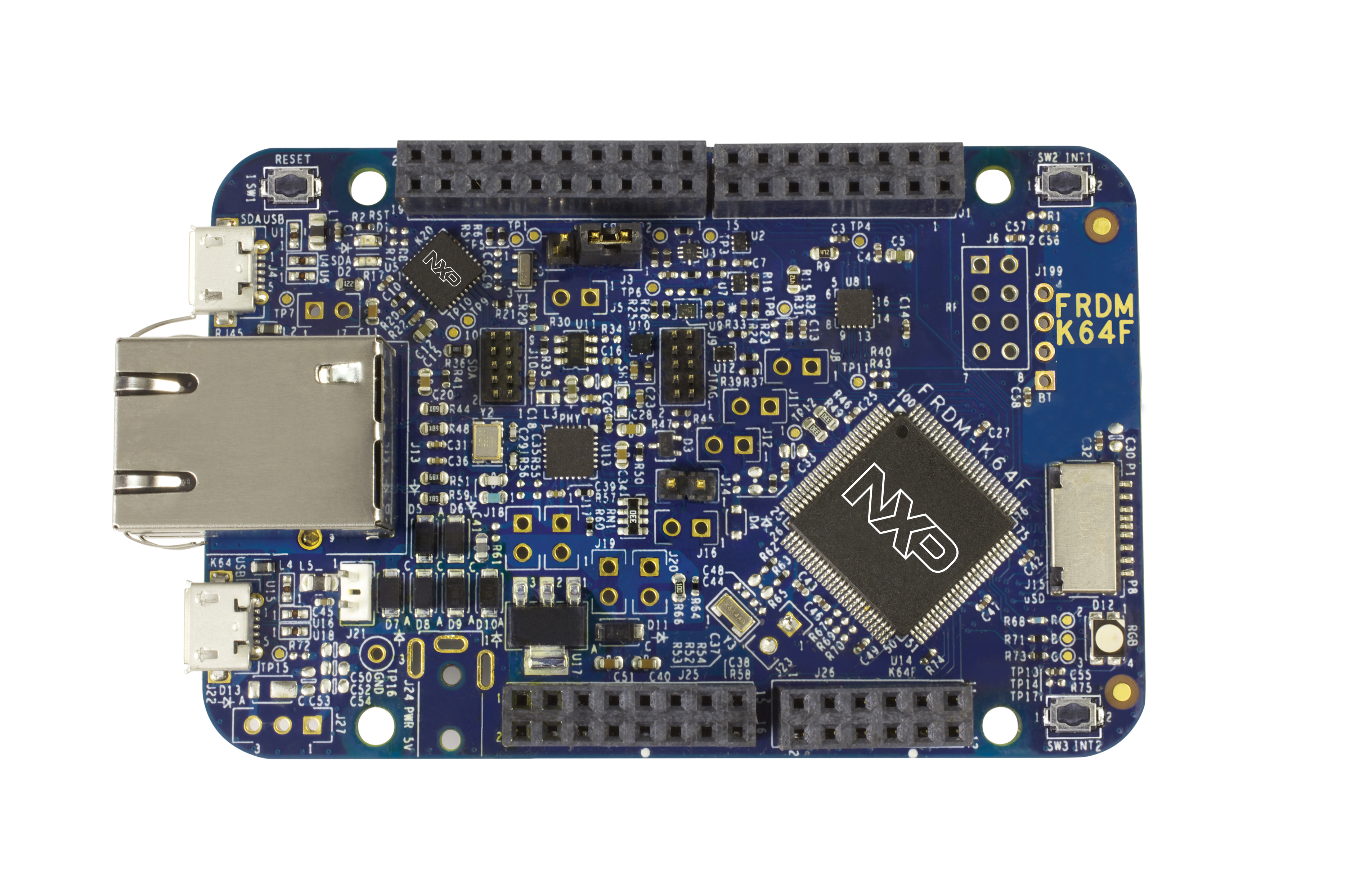
The Freedom-K64F is an ultra-low-cost development platform for Kinetis K64, K63, and K24 MCUs.
- Form-factor compatible with the Arduino R3 pin layout
- Peripherals enable rapid prototyping, including a 6-axis digital accelerometer and magnetometer to create full eCompass capabilities, a tri-colored LED and 2 user push-buttons for direct interaction, a microSD card slot, and connectivity using onboard Ethernet port and headers for use with Bluetooth* and 2.4 GHz radio add-on modules
- OpenSDAv2, the NXP open source hardware embedded serial and debug adapter running an open source bootloader, offers options for serial communication, flash programming, and run-control debugging
Hardware
- MK64FN1M0VLL12 MCU (120 MHz, 1 MB flash memory, 256 KB RAM, low-power, crystal-less USB, and 100 Low profile Quad Flat Package (LQFP))
- Dual role USB interface with micro-B USB connector
- RGB LED
- FXOS8700CQ accelerometer and magnetometer
- Two user push buttons
- Flexible power supply option - OpenSDAv2 USB, Kinetis K64 USB, and external source
- Easy access to MCU input/output through Arduino* R3 compatible I/O connectors
- Programmable OpenSDAv2 debug circuit supporting the CMSIS-DAP Interface
software that provides:
- Mass storage device (MSD) flash programming interface
- CMSIS-DAP debug interface over a driver-less USB HID connection providing run-control debugging and compatibility with IDE tools
- Virtual serial port interface
- Open source CMSIS-DAP software project
- Ethernet
- SDHC
For more information about the K64F SoC and FRDM-K64F board:
- K64F Website
- K64F Datasheet
- K64F Reference Manual
- FRDM-K64F Website
- FRDM-K64F User Guide
- FRDM-K64F Schematics
Supported Features
The frdm_k64f board configuration supports the following hardware features:
| Interface | Controller | Driver/Component |
|---|---|---|
| NVIC | on-chip | nested vector interrupt controller |
| SYSTICK | on-chip | systick |
| PINMUX | on-chip | pinmux |
| GPIO | on-chip | gpio |
| I2C | on-chip | i2c |
| SPI | on-chip | spi |
| ADC | on-chip | adc |
| PWM | on-chip | pwm |
| ETHERNET | on-chip | ethernet |
| UART | on-chip | serial port-polling; serial port-interrupt |
| FLASH | on-chip | soc flash |
| SENSOR | off-chip | fxos8700 polling; fxos8700 trigger |
The default configuration can be found in the defconfig file:
boards/arm/frdm_k64f/frdm_k64f_defconfig
Other hardware features are not currently supported by the port.
Connections and IOs
The K64F SoC has five pairs of pinmux/gpio controllers.
| Name | Function | Usage |
|---|---|---|
| PTB22 | GPIO | Red LED |
| PTE26 | GPIO | Green LED |
| PTB21 | GPIO | Blue LED |
| PTC6 | GPIO | SW2 / FXOS8700 INT1 |
| PTC13 | GPIO | FXOS8700 INT2 |
| PTA4 | GPIO | SW3 |
| PTB10 | ADC | ADC1 channel 14 |
| PTB16 | UART0_RX | UART Console |
| PTB17 | UART0_TX | UART Console |
| PTC8 | PWM | PWM_3 channel 4 |
| PTC9 | PWM | PWM_3 channel 5 |
| PTC16 | UART3_RX | UART BT HCI |
| PTC17 | UART3_TX | UART BT HCI |
| PTCD0 | SPI0_PCS0 | SPI |
| PTCD1 | SPI0_SCK | SPI |
| PTCD2 | SPI0_SOUT | SPI |
| PTCD3 | SPI0_SIN | SPI |
| PTE24 | I2C0_SCL | I2C / FXOS8700 |
| PTE25 | I2C0_SDA | I2C / FXOS8700 |
| PTA5 | MII0_RXER | Ethernet |
| PTA12 | MII0_RXD1 | Ethernet |
| PTA13 | MII0_RXD0 | Ethernet |
| PTA14 | MII0_RXDV | Ethernet |
| PTA15 | MII0_TXEN | Ethernet |
| PTA16 | MII0_TXD0 | Ethernet |
| PTA17 | MII0_TXD1 | Ethernet |
| PTA28 | MII0_TXER | Ethernet |
| PTB0 | MII0_MDIO | Ethernet |
| PTB1 | MII0_MDC | Ethernet |
| PTC16 | ENET0_1588_TMR0 | Ethernet |
| PTC17 | ENET0_1588_TMR1 | Ethernet |
| PTC18 | ENET0_1588_TMR2 | Ethernet |
| PTC19 | ENET0_1588_TMR3 | Ethernet |
Note
Do not enable Ethernet and UART BT HCI simultaneously because they conflict on PTC16-17.
System Clock
The K64F SoC is configured to use the 50 MHz external oscillator on the board with the on-chip PLL to generate a 120 MHz system clock.
Serial Port
The K64F SoC has six UARTs. One is configured for the console, another for BT HCI, and the remaining are not used.
Programming and Debugging
The FRDM-K64F includes the NXP OpenSDA serial and debug adapter built into the board to provide debugging, flash programming, and serial communication over USB.
To use the pyOCD tools with OpenSDA, follow the instructions in the
pyOCD page using the DAPLink FRDM-K64F Firmware. The
pyOCD tools are the default for this board, therefore it is not necessary to
set OPENSDA_FW=daplink explicitly when you invoke make flash or make
debug.
To use the Segger J-Link tools with OpenSDA, follow the instructions in the
Segger J-Link page using the Segger J-Link OpenSDA V2.1 Firmware.
The Segger J-Link tools are not the default for this board, therefore it is
necessary to set OPENSDA_FW=jlink explicitly when you invoke make
debug.
Flashing
This example uses the Hello World sample with the
pyOCD tools. Use the make flash build target to build
your Zephyr application, invoke the pyOCD flash tool and program your Zephyr
application to flash.
$ cd <zephyr_root_path>
$ . zephyr-env.sh
$ cd samples/hello_world/
$ make BOARD=frdm_k64f flash
Open a serial terminal (minicom, putty, etc.) with the following settings:
- Speed: 115200
- Data: 8 bits
- Parity: None
- Stop bits: 1
Reset the board and you should be able to see on the corresponding Serial Port the following message:
Hello World! arm
Debugging
This example uses the Hello World sample with the
pyOCD tools. Use the make debug build target to build
your Zephyr application, invoke the pyOCD GDB server, attach a GDB client, and
program your Zephyr application to flash. It will leave you at a gdb prompt.
$ cd <zephyr_root_path>
$ . zephyr-env.sh
$ cd samples/hello_world/
$ make BOARD=frdm_k64f debug