DA1469x Development Kit Pro
Overview
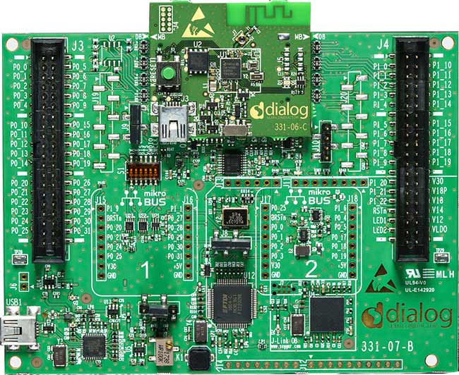
The DA1469x Development Kit Pro hardware provides support for the Renesas DA1469x ARM Cortex-M33 MCU family. The development kit consist of a motherboard with connectors and integrated debugger and an interchangeable daughterboard with an actual MCU (e.g. DA14695 or DA14699).

DA14695 Development Kit Pro (Credit: Renesas Electronics Corporation)
Hardware
DA1469x Development Kit Pro has two external oscillators. The frequency of the sleep clock is 32768 Hz. The frequency of the system clock is 32 MHz.
Supported Features
The _da1469x_dk_pro board configuration supports the following hardware features:
Interface |
Controller |
Driver/Component |
|---|---|---|
FLASH |
on-chip |
flash |
GPIO |
on-chip |
gpio |
MPU |
on-chip |
arch/arm |
NVIC |
on-chip |
arch/arm |
RTT |
Segger |
console |
UART |
on-chip |
serial |
SPI |
on-chip |
spi |
Other hardware features, including the Configurable MAC (CMAC) controller, are currently not supported by the port.
For more information about the DA14695 Development Kit see:
System Clock
The DA1469x Development Kit Pro is configured to use the 32 MHz external oscillator on the board.
Connections and IOs
The DA1469x Development Kit Pro has one LED and one push button which can be used by applications. The UART is connected to on-board serial converter and accessible via USB1 port on motherboard.
The pin connections are as follows:
LED (red), located on daughterboard = P1.01
BUTTON, located on motherboard = P0.06
UART RX, via USB1 on motherboard = P0.08
UART TX, via USB1 on motherboard = P0.09
Programming and Debugging
Applications for the da1469x_dk_pro board configuration can be
built, flashed, and debugged in the usual way. See
Building an Application and Run an Application for more details on
building and running.
Flashing
The DA1469x boots from an external flash connected to QSPI interface. The image written to flash has to have proper header prepended. The process is simplified by using dedicated eZFlashCLI [4] tool that takes care of writing header and can handle different types of flash chips connected to DA1469x MCU. Follow instructions on ezFlashCLI [4] to install the tool. Once installed, flashing can be done in the usual way.
# From the root of the zephyr repository
west build -b da1469x_dk_pro samples/basic/blinky
west flash
Debugging
The DA1469x Development Kit Pro includes a J-Link [3] adaptor built-in on motherboard which provides both debugging interface and serial port. Application can be debugged in the usual way once DA1469x Development Kit Pro is connected to PC via USB port on motherboard.