EFR32-SLWSTK6061A
Overview
The EFR32 Flex Gecko Wireless Starter Kit SLWSTK6061A contains a Wireless System-On-Chip from the EFR32FG family built on an ARM® Cortex®-M4F processor with excellent low power capabilities.
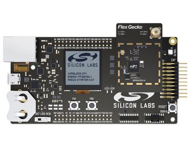
EFR32-SLWSTK6061A (image courtesy of Silicon Labs)
Hardware
The SLWRB4250B radio board plugs into the Wireless Starter Kit Mainboard BRD4001A.
Wireless Starter Kit Mainboard:
- Advanced Energy Monitoring provides real-time information about the energy consumption of an application or prototype design.
- Ultra-low power 128x128 pixel memory LCD
- 2 user buttons and 2 LEDs
- Si7021 Humidity and Temperature Sensor
- On-board Segger J-Link USB and Ethernet debugger
Radio Board:
- EFR32FG1P133F256GM48 Flex Gecko SoC
- 8Mbit SPI NOR Flash
For more information about the EFR32FG1 SoC and EFR32-SLWSTK6061A board, refer to these documents:
- EFR32FG Website
- EFR32FG1 Datasheet
- EFR32xG1 Reference Manual
- EFR32-SLWSTK6061A Website
- EFR32-SLWSTK6061A User Guide
- WSTK Main Board BRD4001A Schematics
- EFR32FG1-BRD4250B Schematics
Supported Features
The efr32_slwstk6061a board configuration supports the following hardware features:
| Interface | Controller | Driver/Component |
|---|---|---|
| NVIC | on-chip | nested vector interrupt controller |
| SYSTICK | on-chip | systick |
| GPIO | on-chip | gpio |
| UART | on-chip | serial port-polling; serial port-interrupt |
The default configuration can be found in the defconfig file:
boards/arm/efr32_slwstk6061a/efr32_slwstk6061a_defconfig
Other hardware features are currently not supported by the port.
Connections and IOs
The EFR32FG1P SoC has five GPIO controllers (PORTA to PORTD and PORTF). All of them are enabled for the EFR32-SLWSTK6061A board.
In the following table, the column Name contains Pin names. For example, PA2 means Pin number 2 on PORTA, as used in the board’s datasheets and manuals.
| Name | Function | Usage |
|---|---|---|
| PF4 | GPIO | LED0 |
| PF5 | GPIO | LED1 |
| PF6 | GPIO | Push Button PB0 |
| PF7 | GPIO | Push Button PB1 |
| PA5 | GPIO | Board Controller Enable EFM_BC_EN |
| PA0 | USART0_TX | UART Console EFM_BC_TX US0_TX #0 |
| PA1 | USART0_RX | UART Console EFM_BC_RX US0_RX #0 |
System Clock
The EFR32FG1P SoC is configured to use the 38.4 MHz external oscillator on the board.
Serial Port
The EFR32FG1P SoC has two USARTs and one Low Energy UARTs (LEUART). USART0 is connected to the board controller and is used for the console.
Programming and Debugging
Note
Before using the kit the first time, you should update the J-Link firmware from J-Link-Downloads
Flashing
The EFR32-SLWSTK6061A includes an J-Link serial and debug adaptor built into the board. The adaptor provides:
- A USB connection to the host computer, which exposes a debug interface and a USB Serial Port.
- A physical UART connection which is relayed over interface USB Serial port.
- An Ethernet connection to support remote debugging.
Flashing an application to EFR32-SLWstk6061A
The sample application Hello World is used for this example. Build the Zephyr kernel and application:
# On Linux/macOS
cd $ZEPHYR_BASE/samples/hello_world
mkdir build && cd build

# On Windows
cd %ZEPHYR_BASE%\samples\hello_world
mkdir build & cd build


# Use cmake to configure a Ninja-based build system:
cmake -GNinja -DBOARD=efr32_slwstk6061a ..

# Now run ninja on the generated build system:
ninja
Connect the EFR32-SLWSTK6061A to your host computer using the USB port and you should see a USB Serial Port. Use J-Link or Silicon Labs Simplicity Studio to flash the generated zephyr.bin.
OpenOCD included in the Zephyr SDK v0.9.3 is too old and does not support the EFR32FG1P chip, neither does the latest OpenOCD 0.10.0 release. You will need to compile the newest version of the source code and install the tool yourself. Modify the following command if you install OpenOCD to a location different than the default /usr/local/.
cmake -GNinja -DBOARD=efr32_slwstk6061a -DOPENOCD=/usr/local/bin/openocd -DOPENOCD_DEFAULT_PATH=/usr/local/share/openocd/scripts ..
ninja flash
Open a serial terminal (minicom, putty, etc.) with the following settings:
- Speed: 115200
- Data: 8 bits
- Parity: None
- Stop bits: 1
Reset the board and you should be able to see on the corresponding Serial Port the following message:
Hello World! arm