ST STM32F072B-DISCO
Overview
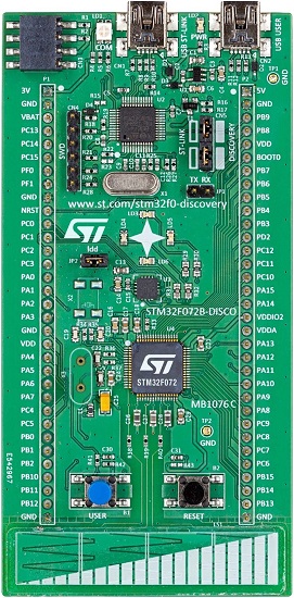
The STM32F072B-DISCO Discovery kit features an ARM Cortex-M0 based STM32F072RB MCU with everything required for beginners and experienced users to get started quickly. Here are some highlights of the STM32F072B-DISCO board:
- STM32 microcontroller in LQFP64 package
- Extension header for LQFP64 I/Os for a quick connection to the prototyping board and easy probing
- On-board ST-LINK/V2, debugger/programmer with SWD connector
- Board power supply: through USB bus or from an external 5 V supply voltage
- External application power supply: 3 V and 5 V
- Six LEDs:
- LD1 (red/green) for USB communication
- LD2 (red) for 3.3 V power on
- Four user LEDs: LD3 (orange), LD4 (green), LD5 (red) and LD6 (blue)
- Two push-buttons: USER and RESET
- USB USER with Mini-B connector
- L3GD20, ST MEMS motion sensor, 3-axis digital output gyroscope
- One linear touch sensor or four touch keys
- RF EEprom daughter board connector
More information about the board can be found at the STM32F072B-DISCO website [1].
Hardware
STM32F072B-DISCO Discovery kit provides the following hardware components:
- STM32F072RBTT6 in LQFP64 package
- ARM® 32-bit Cortex® -M0 CPU
- 48 MHz max CPU frequency
- VDD from 2.0 V to 3.6 V
- 128 KB Flash
- 16 KB SRAM
- GPIO with external interrupt capability
- 12-bit ADC with 39 channels
- 12-bit D/A converters
- RTC
- General Purpose Timers (12)
- USART/UART (4)
- I2C (2)
- SPI (2)
- CAN
- USB 2.0 full speed interface
- DMA Controller
- 24 capacitive sensing channels for touchkey, linear and rotary touch sensors
- More information about STM32F072RB can be found here:
Supported Features
The Zephyr stm32f072b_disco board configuration supports the following hardware features:
| Interface | Controller | Driver/Component |
|---|---|---|
| NVIC | on-chip | nested vector interrupt controller |
| UART | on-chip | serial port-polling; serial port-interrupt |
| PINMUX | on-chip | pinmux |
| GPIO | on-chip | gpio |
| CLOCK | on-chip | reset and clock control |
| IWDG | on-chip | independent watchdog |
| I2C | on-chip | i2c controller |
| SPI | on-chip | SPI controller |
Other hardware features are not yet supported in this Zephyr port.
The default configuration can be found in the defconfig file:
boards/arm/stm32f072b_disco/stm32f072b_disco_defconfig
Pin Mapping
STM32F072B-DISCO Discovery kit has 6 GPIO controllers. These controllers are responsible for pin muxing, input/output, pull-up, etc.
For mode details please refer to STM32F072B-DISCO board User Manual [2].
Default Zephyr Peripheral Mapping:
- UART_1_TX : PB6
- UART_1_RX : PB7
- I2C1_SCL : PB8
- I2C1_SDA : PB9
- I2C2_SCL : PB10
- I2C2_SDA : PB11
- SPI1_SCK : PB3
- SPI1_MISO : PB4
- SPI1_MOSI : PB5
- USER_PB : PA0
- LD3 : PC6
- LD4 : PC8
- LD5 : PC9
- LD6 : PC7
System Clock
STM32F072B-DISCO System Clock could be driven by internal or external oscillator, as well as main PLL clock. By default System clock is driven by PLL clock at 72 MHz, driven by internal 8 MHz oscillator.
Serial Port
STM32F072B-DISCO Discovery kit has up to 4 UARTs. The Zephyr console output is assigned to UART 1. Default settings are 115200 8N1.
Programming and Debugging
Applications for the stm32f072b_disco board configuration can be built and
flashed in the usual way (see Build an Application and
Run an Application for more details).
Flashing
STM32F072B-DISCO board includes an ST-LINK/V2 embedded debug tool interface. This interface is supported by the openocd version included in the Zephyr SDK.
Flashing an application to STM32F072B-DISCO
First, connect the STM32F072B-DISCO Discovery kit to your host computer using the USB port to prepare it for flashing. Then build and flash your application.
Here is an example for the Hello World application.
# On Linux/macOS
cd $ZEPHYR_BASE/samples/hello_world
mkdir build && cd build

# On Windows
cd %ZEPHYR_BASE%\samples\hello_world
mkdir build & cd build


# Use cmake to configure a Ninja-based build system:
cmake -GNinja -DBOARD=stm32f072b_disco ..

# Now run ninja on the generated build system:
ninja
ninja flash
Run a serial host program to connect with your board. A TTL(3.3V) serial adapter is required.
$ minicom -D /dev/<tty device>
Replace <tty_device> with the port where the serial adapter can be found. For example, under Linux, /dev/ttyUSB0.
You should see the following message on the console:
Hello World! arm
Debugging
You can debug an application in the usual way. Here is an example for the Hello World application.
# On Linux/macOS
cd $ZEPHYR_BASE/samples/hello_world
mkdir build && cd build

# On Windows
cd %ZEPHYR_BASE%\samples\hello_world
mkdir build & cd build


# Use cmake to configure a Ninja-based build system:
cmake -GNinja -DBOARD=stm32f072b_disco ..

# Now run ninja on the generated build system:
ninja debug