ST STM32F4DISCOVERY
Overview
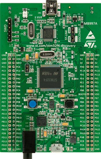
The STM32F4DISCOVERY Discovery kit features an ARM Cortex-M4 based STM32F407VG MCU with a wide range of connectivity support and configurations Here are some highlights of the STM32F4DISCOVERY board:
STM32 microcontroller in LQFP100 package
Extension header for all LQFP100 I/Os for quick connection to prototyping board and easy probing
On-board ST-LINK/V2 debugger/programmer with SWD connector
Flexible board power supply:
- USB VBUS or external source(3.3V, 5V, 7 - 12V)
- Power management access point
Eight LEDs:
- USB communication (LD1)
- 3.3 V power on (LD2)
- Four user LEDs: orange (LD3), green (LD4), red (LD5), and blue (LD6)
- 2 USB OTG LEDs for VBUS (LD7) and over-current (LD8)
Two push-buttons: USER and RESET
USB OTG FS with micro-AB connector
LIS302DL or LIS3DSH ST MEMS 3-axis accelerometer
MP45DT02 ST-MEMS audio sensor omni-directional digital microphone
CS43L22 audio DAC with integrated class D speaker driver
More information about the board can be found at the STM32F4DISCOVERY website.
Hardware
STM32F4DISCOVERY Discovery kit provides the following hardware components:
- STM32F407VGT6 in LQFP100 package
- ARM® 32-bit Cortex® -M4 CPU with FPU
- 168 MHz max CPU frequency
- VDD from 1.8 V to 3.6 V
- 1 MB Flash
- 192+4 KB SRAM including 64-Kbyte of core coupled memory
- GPIO with external interrupt capability
- 3x12-bit ADC with 24 channels
- 2x12-bit D/A converters
- RTC
- Advanced-control Timer
- General Purpose Timers (17)
- Watchdog Timers (2)
- USART/UART (6)
- I2C (3)
- SPI (3)
- SDIO
- 2xCAN
- USB 2.0 OTG FS with on-chip PHY
- USB 2.0 OTG HS/FS with dedicated DMA, on-chip full-speed PHY and ULPI
- 10/100 Ethernet MAC with dedicated DMA
- 8- to 14-bit parallel camera
- CRC calculation unit
- True random number generator
- DMA Controller
- More information about STM32F407VG can be found here:
Supported Features
The Zephyr stm32f4_disco board configuration supports the following hardware features:
| Interface | Controller | Driver/Component |
|---|---|---|
| NVIC | on-chip | nested vector interrupt controller |
| UART | on-chip | serial port-polling; serial port-interrupt |
| PINMUX | on-chip | pinmux |
| GPIO | on-chip | gpio |
| PWM | on-chip | pwm |
Other hardware features are not yet supported on Zephyr porting.
The default configuration can be found in the defconfig file:
boards/arm/stm32f4_disco/stm32f4_disco_defconfig
Pin Mapping
STM32F4DISCOVERY Discovery kit has 8 GPIO controllers. These controllers are responsible for pin muxing, input/output, pull-up, etc.
For mode details please refer to STM32F4DISCOVERY board User Manual.
Default Zephyr Peripheral Mapping:
- UART_1_TX : PB6
- UART_1_RX : PB7
- UART_2_TX : PA2
- UART_2_RX : PA3
- USER_PB : PA0
- LD3 : PD13
- LD4 : PD12
- LD5 : PD14
- LD6 : PD15
System Clock
STM32F4DISCOVERY System Clock could be driven by internal or external oscillator, as well as main PLL clock. By default System clock is driven by PLL clock at 168MHz, driven by 8MHz high speed external clock.
Serial Port
STM32F4DISCOVERY Discovery kit has up to 6 UARTs. The Zephyr console output is assigned to UART2. Default settings are 115200 8N1.
Programming and Debugging
Applications for the stm32f4_disco board configuration can be built and
flashed in the usual way (see Build an Application and
Run an Application for more details).
Flashing
STM32F4DISCOVERY Discovery kit includes an ST-LINK/V2 embedded debug tool interface. This interface is supported by the openocd version included in Zephyr SDK.
Flashing an application to STM32F4DISCOVERY
Here is an example for the Hello World application.
Run a serial host program to connect with your board:
$ minicom -D /dev/ttyACM0
Build and flash the application:
# On Linux/macOS
cd $ZEPHYR_BASE/samples/hello_world
mkdir build && cd build

# On Windows
cd %ZEPHYR_BASE%\samples\hello_world
mkdir build & cd build


# Use cmake to configure a Ninja-based build system:
cmake -GNinja -DBOARD=stm32f4_disco ..

# Now run ninja on the generated build system:
ninja
ninja flash
You should see the following message on the console:
Hello World! arm
Debugging
You can debug an application in the usual way. Here is an example for the Hello World application.
# On Linux/macOS
cd $ZEPHYR_BASE/samples/hello_world
# If you already made a build directory (build) and ran cmake, just 'cd build' instead.
mkdir build && cd build

# On Windows
cd %ZEPHYR_BASE%\samples\hello_world
# If you already made a build directory (build) and ran cmake, just 'cd build' instead.
mkdir build & cd build

# If you already made a build directory (build) and ran cmake, just 'cd build' instead.

# Use cmake to configure a Ninja-based build system:
cmake -GNinja -DBOARD=stm32f4_disco ..

# Now run ninja on the generated build system:
ninja debug