NXP LPCXPRESSO54114 (M4 Core)
Overview
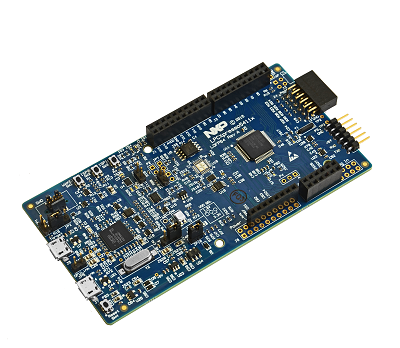
The LPCXpresso54114 board has been developed by NXP to enable evaluation of and prototyping with the LPC54110 family of MCUs and with the low-power LPC54110 family of MCUs. LPCXpresso* is a low-cost development platform available from NXP supporting NXP’s ARM-based microcontrollers. LPCXpresso is an end-to-end solution enabling embedded engineers to develop their applications from initial evaluation to final production.
Hardware
- LPC54114 dual-core (M4F and dual M0) MCU running at up to 100 MHz
- On-board high-speed USB based debug probe with CMSIS-DAP and J-Link protocol support, can debug the on-board LPC54114 or an external target
- External debug probe option
- Tri-color LED, target Reset, ISP & interrupt/user buttons for easy testing of software functionality
- Expansion options based on Arduino UNO and Pmod™, plus additional expansion port pins
- On-board 1.8 V and 3.3 V regulators plus external power supply option
- 8 Mb Macronix MX25R SPI flash
- Built-in MCU power consumption and supply voltage measurement
- UART, I²C and SPI port bridging from LPC54114 target to USB via the on-board debug probe
- FTDI UART connector
For more information about the LPC54114 SoC and LPCXPRESSO54114 board:
- LPC54114 SoC Website
- LPC54114 Datasheet
- LPC54114 Reference Manual
- LPCXPRESSO54114 Website
- LPCXPRESSO54114 User Guide
- LPCXPRESSO54114 Schematics
Supported Features
The lpcxpresso54114 board configuration supports the following hardware features:
| Interface | Controller | Driver/Component |
|---|---|---|
| NVIC | on-chip | nested vector interrupt controller |
| SYSTICK | on-chip | systick |
| IOCON | on-chip | pinmux |
| GPIO | on-chip | gpio |
| USART | on-chip | serial port-polling |
The default configuration can be found in the defconfig file:
boards/arm/lpcxpresso54114_m4/lpcxpresso54114_m4_defconfig
Other hardware features are not currently supported by the port.
Connections and IOs
The LPC54114 SoC has IOCON registers, which can be used to configure the functionality of a pin.
| Name | Function | Usage |
|---|---|---|
| PIO0_0 | USART | USART RX |
| PIO0_1 | USART | USART TX |
| PIO0_29 | GPIO | RED LED |
| PIO1_9 | GPIO | BLUE_LED |
| PIO1_10 | GPIO | GREEN LED |
System Clock
The LPC54114 SoC is configured to use the internal FRO at 48MHz as a source for the system clock. Other sources for the system clock are provided in the SOC, depending on your system requirements.
Serial Port
The LPC54114 SoC has 8 FLEXCOMM interfaces for serial communication. One is configured as USART for the console and the remaining are not used.
Programming and Debugging
The LPCXpresso54114 includes the LPC-Link2 serial and debug adapter built into the board to provide debugging, flash programming, and serial communication over USB. LPC-Link2 can be configured with Segger J-Link or CMSIS-DAP firmware variants to support corresponding debug tools. Currently only the Segger J-Link tools are supported for this board in Zephyr, therefore you should use the Segger J-Link firmware variant.
Before you start using Zephyr on the LPCXpresso54114, download and run
LPCScrypt to update the LPC-Link2 firmware to the latest version, currently
Firmware_JLink_LPC-Link2_20160923.bin. Serial communication problems, such
as dropping characters, have been observed with older versions of the firmware.
Debugging
You can debug an application in the usual way. Here is an example for the Hello World application.
# On Linux/macOS
cd $ZEPHYR_BASE/samples/hello_world
mkdir build && cd build

# On Windows
cd %ZEPHYR_BASE%\samples\hello_world
mkdir build & cd build


# Use cmake to configure a Ninja-based build system:
cmake -GNinja -DBOARD=lpcxpresso54114_m4 ..

# Now run ninja on the generated build system:
ninja debug
Open a serial terminal (minicom, putty, etc.) and connect the board with the following settings:
- Speed: 115200
- Data: 8 bits
- Parity: None
- Stop bits: 1
Reset the board and the following message will appear on the corresponding serial port:
Hello World! arm