OLIMEXINO-STM32
Overview
Zephyr applications use the olimexino_stm32 board configuration to run on the OLIMEXINO-STM32 open source hardware. It based on the STMicroelectronics STM32F103RB ARM Cortex-M3 CPU.
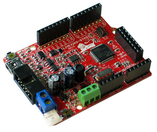
OLIMEXINO-STM32
More information about the board can be found at the OLIMEXINO-STM32 website and OLIMEXINO-STM32 user manual. The ST STM32F103xB Datasheet contains the processor’s information and the datasheet.
Supported Features
The olimexino_stm32 board configuration supports the following hardware features:
| Interface | Controller | Driver/Component |
|---|---|---|
| NVIC | on-chip | nested vectored interrupt controller |
| SYSTICK | on-chip | system clock |
| UART | on-chip | serial port |
| GPIO | on-chip | gpio |
| I2C | on-chip | i2c |
| SPI | on-chip | spi |
| USB | on-chip | USB device |
Other hardware features are not supported by the Zephyr kernel.
Pin Mapping
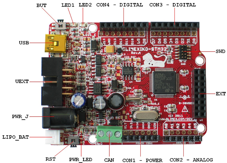
OLIMEXINO-STM32 connectors
LED
- LED1 (green) = PA5
- LED2 (yellow) = PA1
- PWR_LED (red) = power
Push buttons
- BUT = PC9 / TIM3CH4 / BOOT0
- RST = NRST
External Connectors
SWD
| PIN # | Signal Name | STM32F103RB Functions |
|---|---|---|
| 1 | VCC | N/A |
| 2 | TMS / SWDIO | JTMS / SWDIO / PA13 |
| 3 | GND | N/A |
| 4 | TCK / SWCLK | JTCK / SWCLK / PA14 |
| 5 | GND | N/A |
| 6 | TDO / SWO | JTDO /TIM2_CH2 / PB3 / TRACESWO / SPI1_SCK |
| 7 | Cut off | N/A |
| 8 | TDI | JTDI / TIM2_CH1_ETR / PA15 / SPI1_NSS |
| 9 | GND | N/A |
| 10 | RESET | NRST |
UEXT
| PIN # | Signal Name | STM32F103RB Functions |
|---|---|---|
| 1 | VCC | N/A |
| 2 | GND | N/A |
| 3 | D7 (TXD1) | PA9 / USART1_TX / TIM1_CH2 |
| 4 | D8 (RXD1) | PA10 / USART1_RX / TIM1_CH3 |
| 5 | D29 (SCL2) | PB10 / I2C2_SCL / USART3_TX / TIM2_CH3 |
| 6 | D30 (SDA2) | PB11 / I2C2_SDA / USART3_RX / TIM2_CH4 |
| 7 | D12 (MISO1) | PA6 / SPI1_MISO / ADC12_IN6 / TIM3_CH1 / TIM1_BKIN |
| 8 | D11 (MOSI1) | PA7 / SPI1_MOSI / ADC12_IN7 / TIM3_CH2 / TIM1_CH1N |
| 9 | D13 (SCK / LED1) | PA5 / SPI1_SCK / ADC12_IN5 |
| 10 | UEXT_#CS | N/A |
EXT
| PIN # | Signal Name | STM32F103RB Functions |
|---|---|---|
| 1 | D23_EXT | PC15 / OSC32_OUT |
| 2 | D24 (CANTX) | PB9 / TIM4_CH4 / I2C1_SDA / CANTX |
| 3 | D25 (MMC_CS) | PD2 / TIM3_ETR |
| 4 | D26 | PC10 / USART3_TX |
| 5 | D27 | PB0 / ADC12_IN8 / TIM3_CH3 / TIM1_CH2N |
| 6 | D28 | PB1 / ADC12_IN9 / TIM3_CH4 / TIM1_CH3N |
| 7 | D29 (SCL2) | PB10 / I2C2_SCL / USART3_TX / TIM2_CH3 |
| 8 | D30 (SDA2) | PB11 / I2C2_SDA / USART3_RX / TIM2_CH4 |
| 9 | D31 (#SS2) | PB12 / SPI2_NSS / I2C2_SMBAI / USART3_CK / TIM1_BKIN |
| 10 | D32 (SCK2) | PB13 / SPI2_SCK/ USART3_CTS / TIM1_CH1N |
| 11 | D33 (MISO2) | PB14 / SPI2_MISO / USART3_RTS / TIM1_CH2N |
| 12 | D34 (MOSI2) | PB15 / SPI2_MOSI / TIM1_CH3N |
| 13 | D35 | PC6 / TIM3_CH1 |
| 14 | D36 | PC7 / TIM3_CH2 |
| 15 | D37 | PC8 / TIM3_CH3 |
| 16 | GND | N/A |
Arduino Headers
CON1 power
| PIN # | Signal Name | STM32F103RB Functions |
|---|---|---|
| 1 | RESET | NRST |
| 2 | VCC (3V3) | N/A |
| 3 | VDD (3V3A) | N/A |
| 4 | GND | N/A |
| 5 | GND | N/A |
| 6 | VIN | N/A |
CON2 analog
| PIN # | Signal Name | STM32F103RB Functions |
|---|---|---|
| 1 | D15 (A0) | PC0 / ADC12_IN10 |
| 2 | D16 (A1) | PC1 / ADC12_IN11 |
| 3 | D17 (A2) | PC2 / ADC12_IN12 |
| 4 | D18 (A3) | PC3 / ADC12_IN13 |
| 5 | D19 (A4) | PC4 / ADC12_IN14 |
| 6 | D20 (A5) | PC5 / ADC12_IN15 |
CON3 digital
| PIN # | Signal Name | STM32F103RB Functions |
|---|---|---|
| 1 | D0 (RXD2) | PA3 / USART2_RX / ADC12_IN3 / TIM2_CH4 |
| 2 | D1 (TXD2) | PA2 / USART2_TX / ADC12_IN2 / TIM2_CH3 |
| 3 | D2 | PA0 / WKUP / USART2_CTS / ADC12_IN0 / TIM2_CH1 |
| 4 | D3 (LED2) | PA1 / USART2_RTS / ADC12_IN1 / TIM2_CH2 |
| 5 | D4 | PB5 / I2C1_SMBAI / TIM3_CH2 / SPI1_MOSI |
| 6 | D5 | PB6 / I2C1_SCL / TIM4_CH1 / USART1_TX |
| 7 | D6 | PA8 / USART1_CK / TIM1_CH1 / MCO |
| 8 | D7 (TXD1) | PA9 / USART1_TX / TIM1_CH2 |
CON4 digital
| PIN # | Signal Name | STM32F103RB Functions |
|---|---|---|
| 1 | D8 (RXD1) | PA10 / USART1_RX / TIM1_CH3 |
| 2 | D9 | PB7 / I2C1_SDA / TIM4_CH2 / USART1_RX |
| 3 | D10 (#SS1) | PA4 / SPI1_NSS / USART2_CK / ADC12_IN4 |
| 4 | D11 (MOSI1) | PA7 / SPI1_MOSI / ADC12_IN7 / TIM3_CH2 / TIM1_CH1N |
| 5 | D12 (MISO1) | PA6 / SPI1_MISO / ADC12_IN6 / TIM3_CH1 / TIM1_BKIN |
| 6 | D13 (SCK1 / LED1) | PA5 / SPI1_SCK / ADC12_IN5 |
| 7 | GND | N/A |
| 8 | D14 (CANRX) | PB8 / TIM4_CH3 / I2C1_SCL / CANRX |
System Clock
OLIMEXINO-STM32 has two external oscillators. The frequency of the slow clock is 32.768 kHz. The frequency of the main clock is 8 MHz. The processor can setup HSE to drive the master clock, which can be set as high as 72 MHz.
Serial Port
OLIMEXINO-STM32 board has up to 3 U(S)ARTs. The Zephyr console output is assigned to USART1. Default settings are 115200 8N1.
SPI
OLIMEXINO-STM32 board has up to 2 SPIs. The default SPI mapping for Zephyr is:
- SPI1_NSS : PA4
- SPI1_SCK : PA5
- SPI1_MISO : PA6
- SPI1_MOSI : PA7
I2C
OLIMEXINO-STM32 board has up to 1 I2C. The default I2C mapping for Zephyr is:
- I2C2_SCL : PB10
- I2C2_SDA : PB11
USB
OLIMEXINO-STM32 board has a USB 2.0 full-speed device interface available through its mini USB connector.
- USB_DM : PA11
- USB_DP : PA12
Jumpers
The Zephyr kernel uses the OLIMEXINO-STM32 default jumper settings. Note that all jumpers on the board are SMD type. You will need to solder, unsolder, or cut them in order to reconfigure them.
The default jumper settings for the OLIMEXIMO-STM32E are:
| Jumper Name | Open | Close |
|---|---|---|
| LED1_E | x | |
| LED2_E | x | |
| D23_E | x | |
| R-T | x | |
| P10_E | x |
| Jumper Name | D10 | D4 |
|---|---|---|
| D10/D4 | x |
Flashing Zephyr onto OLIMEXINO-STM32
Flashing the Zephyr kernel onto OLIMEXINO-STM32 requires the stm32flash tool.
Building stm32flash command line tool
To build the stm32flash tool, follow the steps below:
- Checkout the stm32flash tool’s code from the repository.
$ git clone http://git.code.sf.net/p/stm32flash/code stm32flash
$ cd stm32flash
- Build the stm32flash tool.
$ make
- The resulting binary is available at
stm32flash.
Flashing an Application to OLIMEXINO-STM32
To upload an application to the OLIMEXINO-STM32 board a TTL(3.3V) serial adapter is required. This tutorial uses the Button demo sample application.
To build the Zephyr kernel and application, enter:
# On Linux/macOS
cd $ZEPHYR_BASE/samples/basic/button
mkdir build && cd build

# On Windows
cd %ZEPHYR_BASE%\samples\basic\button
mkdir build & cd build


# Use cmake to configure a Ninja-based build system:
cmake -GNinja -DBOARD=olimexino_stm32 ..

# Now run ninja on the generated build system:
ninja
Connect the serial cable to the UEXT lines of the UART interface (pin #3=TX and pin #4=RX).
Power the OLIMEXINO-STM32 via the mini USB.
Reset the board while holding the button (BUT).
Flash the application using the stm32flash tool. Start by navigating to the build directory containing zephyr.bin.
$ stm32flash -w zephyr.bin -v -g 0x0 <tty_device>Replace
<tty_device>with the port where the board OLIMEXINO-STM32 can be found. For example, under Linux,/dev/ttyUSB0.Run your favorite terminal program to listen for output.
$ minicom -D /dev/ttyUSB0 -b 115200
The
-boption sets baud rate ignoring the value from config.Press the Reset button and you should see the output of button application in your terminal. The state of the BUT button’s GPIO line is monitored and printed to the serial console. When the input button gets pressed, the interrupt handler prints information about this event along with its timestamp.
Note
Make sure your terminal program is closed before flashing the binary image, or it will interfere with the flashing process.