OLIMEX-STM32-E407
Overview
Zephyr applications use the olimex_stm32_e407 board configuration to run on the OLIMEX-STM32-E407 open source hardware. It is based on the STMicroelectronics STM32F407ZG ARM Cortex-M4 CPU.
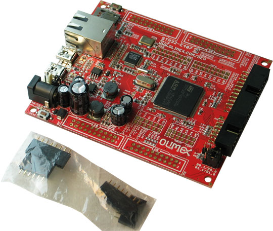
OLIMEX-STM32-E407
Hardware
Information about the board can be found at the OLIMEX-STM32-E407 website and OLIMEX-STM32-E407 user manual. The ST STM32F407ZG Datasheet contains the processor’s information and the datasheet.
Supported Features
The olimex_stm32_e407 board configuration supports the following hardware features:
| Interface | Controller | Driver/Component |
|---|---|---|
| NVIC | on-chip | nested vectored interrupt controller |
| SYSTICK | on-chip | system clock |
| UART | on-chip | serial port |
| GPIO | on-chip | gpio |
Other hardware features are not supported by the Zephyr kernel.
Pin Mapping
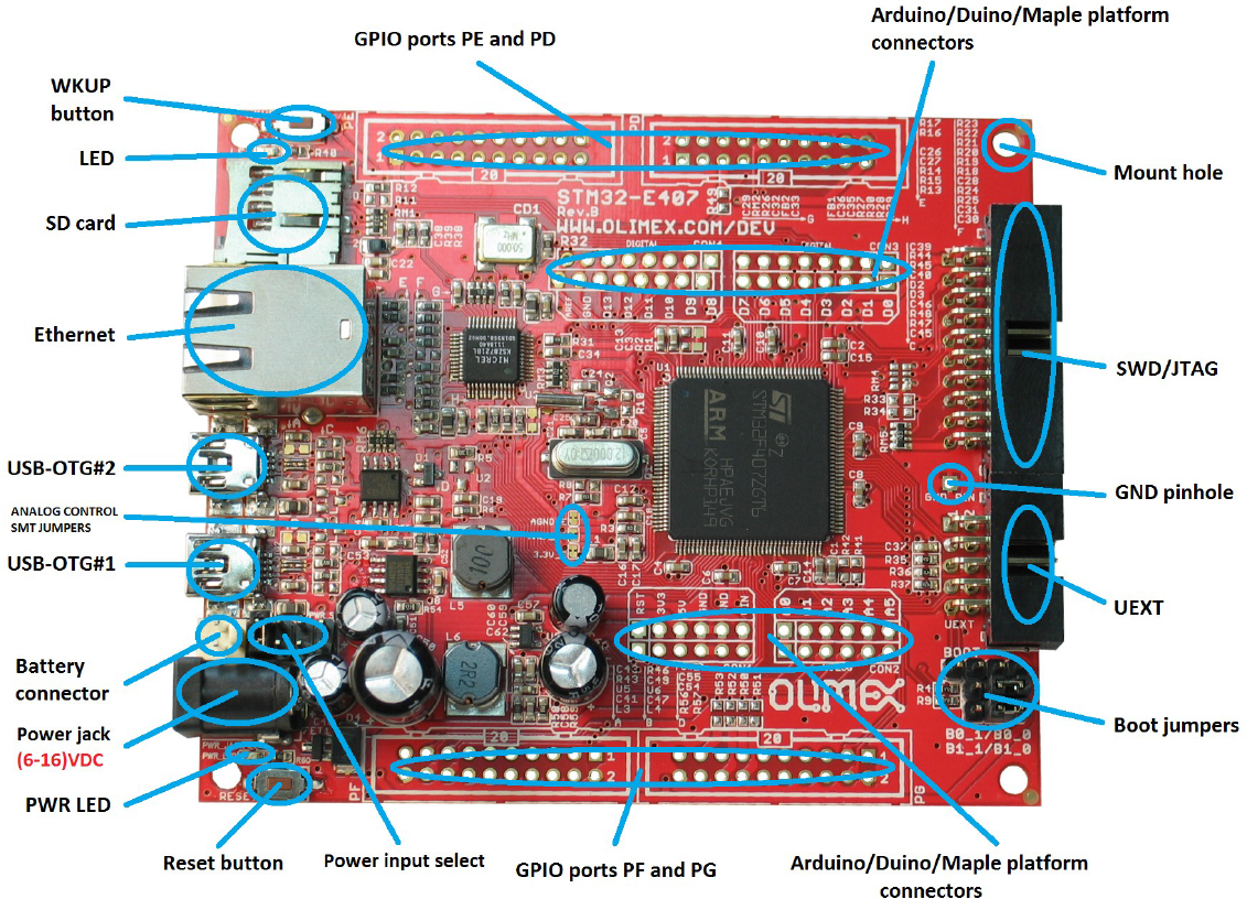
OLIMEX-STM32-E407 connectors
LED
- LED (green) = PC13
- PWR_LED (red) = power
Push buttons
- BUT = PA0
- RST = NRST
External Connectors
JTAG/SWD debug
| PIN # | Signal Name | Pin # | Signal Name |
|---|---|---|---|
| 1 | +3.3V | 11 | |
| 2 | +3.3V | 12 | GND |
| 3 | PB4 / TRST | 13 | PB3 / TDO |
| 4 | GND | 14 | GND |
| 5 | PA15 / TDI | 15 | PB4 / TRST |
| 6 | GND | 16 | GND |
| 7 | PA13 / TMS | 17 | |
| 8 | GND | 18 | GND |
| 9 | PA14 / TCK | 19 | +5V_JTAG |
| 10 | GND | 20 | GND |
UEXT
| PIN # | Wire Name | STM32F407 port |
|---|---|---|
| 1 | +3.3V | |
| 2 | GND | |
| 3 | PC6/USART6_TX | PC6 |
| 4 | PC7/USART6_RX | PC7 |
| 5 | PB8/I2C1_SCL | PB8 |
| 6 | PB9/I2C1_SDA | PB9 |
| 7 | PC2/SPI2_MISO | PC2 |
| 8 | PC3/SPI2_MOSI | PC3 |
| 9 | PB10/SPI_SCK/UART3_TX | PB10 |
| 10 | RB7/UEXT_CS | PB7 |
Arduino Headers
CON1 power
| Pin | Signal Name | STM32F407 Pin# |
|---|---|---|
| RST | RESET | 25 |
| 3V3 | VCC (3V3) | N/A |
| 5V | VDD (5V) | N/A |
| GND | GND | N/A |
| GND | GND | N/A |
| VIN | VIN | N/A |
CON2 analog
| Pin | Signal Name | STM32F407 Pin# |
|---|---|---|
| A0 | PC0 | 26 |
| A1 | PF6 | 18 |
| A2 | PF7 | 19 |
| A3 | PF8 | 20 |
| A4 | PF9 | 21 |
| A5 | PF10 | 22 |
CON3 digital
| Pin | Signal Name | STM32F407 Pin# |
|---|---|---|
| D0 | PB7/USART1_RX | 137 |
| D1 | PB6/USART1_TX | 136 |
| D2 | PE2 | 1 |
| D3 | PE4 | 3 |
| D4 | PE5 | 4 |
| D5 | PR6 | 5 |
| D6 | PG7 | 92 |
| D7 | PG8 | 93 |
CON4 digital
| Pin | Signal Name | STM32F407 Pin# |
|---|---|---|
| D8 | PG12 | 35 |
| D9 | PG15 | 70 |
| D10 | PA4 | 40 |
| D11 | PB5 | 43 |
| D12 | PA6 | 42 |
| D13 | PA5 | 41 |
| GND | AGND | 31 |
| AREF | AREF | 32 |
PD
| PIN # | Signal Name | Pin # | Signal Name |
|---|---|---|---|
| 1 | +3.3V | 11 | PD8 |
| 2 | GND | 12 | PD9 |
| 3 | PD0 | 13 | PD10 |
| 4 | PD1 | 14 | PD11 |
| 5 | PD2/SD_MMC | 15 | PD12 |
| 6 | PD3 | 16 | PD13 |
| 7 | PD4 | 17 | PD14 |
| 8 | PD5 | 18 | PD15 |
| 9 | PD6 | 19 | +5V |
| 10 | PD7 | 20 | GND |
PE
| PIN # | Signal Name | Pin # | Signal Name |
|---|---|---|---|
| 1 | +3.3V | 11 | PE8 |
| 2 | GND | 12 | PE9 |
| 3 | PE0 | 13 | PE10 |
| 4 | PE1 | 14 | PE11 |
| 5 | PE2/D2 | 15 | PE12 |
| 6 | PE3 | 16 | PE13 |
| 7 | PE4/D3 | 17 | PE14 |
| 8 | PE5/D4 | 18 | PE15 |
| 9 | PE6/D5 | 19 | +5V |
| 10 | PE7 | 20 | GND |
PF
| PIN # | Signal Name | Pin # | Signal Name |
|---|---|---|---|
| 1 | +3.3V | 11 | PF8/A3 |
| 2 | GND | 12 | PF9/A4 |
| 3 | PF0 | 13 | PF10/A5 |
| 4 | PF1 | 14 | PF11/A6 |
| 5 | PF2 | 15 | PF12 |
| 6 | PF3 | 16 | PF13 |
| 7 | PF4 | 17 | PF14 |
| 8 | PF5 | 18 | PF15 |
| 9 | PF6/A1 | 19 | +5V |
| 10 | PF7/A2 | 20 | GND |
PG
| PIN # | Signal Name | Pin # | Signal Name |
|---|---|---|---|
| 1 | +3.3V | 11 | PG8/D7 |
| 2 | GND | 12 | PG9 |
| 3 | PG0 | 13 | PG10/UEXT_CS |
| 4 | PG1 | 14 | PG11/TX_EN |
| 5 | PG2 | 15 | PG12/D8 |
| 6 | PG3 | 16 | PG13/TXD0 |
| 7 | PG4 | 17 | PG14/TXD1 |
| 8 | PG5 | 18 | PG15/D9 |
| 9 | PG6 | 19 | +5V |
| 10 | PG7/D6 | 20 | GND |
System Clock
OLIMEX-STM32-E407 has two external oscillators. The frequency of the slow clock is 32.768 kHz. The frequency of the main clock is 12 MHz. The processor can setup HSE to drive the master clock, which can be set as high as 168 MHz.
Programming and Debugging
The OLIMEX-STM32-E407 board does not include an embedded debug tool interface. You will need to use ST tools or an external JTAG probe. In the following examples a ST-Link V2 USB dongle is used.
If you have an external JTAG probe compliant with the default Zephyr OpenOCD
configuration, however, then applications for the olimex_stm32_e407 board
configuration can be built and flashed in the usual way (see
Build an Application and Run an Application for more details).
Flashing an application to the Olimex-STM32-E407
Connect the ST-Link USB dongle to your host computer and to the JTAG port of the OLIMEX-STM32-E407 board. Then build and flash an application.
Here is an example for the Hello World application.
# On Linux/macOS
cd $ZEPHYR_BASE/samples/hello_world
mkdir build && cd build

# On Windows
cd %ZEPHYR_BASE%\samples\hello_world
mkdir build & cd build


# Use cmake to configure a Ninja-based build system:
cmake -GNinja -DBOARD=olimex_stm32_e407 ..

# Now run ninja on the generated build system:
ninja
ninja flash
Run a serial host program to connect with your board:
$ minicom -D /dev/ttyACM0
After resetting the board, you should see the following message:
***** BOOTING ZEPHYR OS v1.8.99 - BUILD: May 29 2017 22:31:53 *****
Hello World! arm
Debugging
Provided that you have a JTAG probe, you can debug an application in the usual way. Here is an example for the Hello World application.
# On Linux/macOS
cd $ZEPHYR_BASE/samples/hello_world
# If you already made a build directory (build) and ran cmake, just 'cd build' instead.
mkdir build && cd build

# On Windows
cd %ZEPHYR_BASE%\samples\hello_world
# If you already made a build directory (build) and ran cmake, just 'cd build' instead.
mkdir build & cd build

# If you already made a build directory (build) and ran cmake, just 'cd build' instead.

# Use cmake to configure a Ninja-based build system:
cmake -GNinja -DBOARD=olimex_stm32_e407 ..

# Now run ninja on the generated build system:
ninja debug