nRF52840-PCA10059
Overview
Zephyr applications use the nrf52840_pca10059 board configuration to run on the nRF52840 PCA10059 (USB Dongle) hardware. It provides support for the Nordic Semiconductor nRF52840 ARM Cortex-M4F CPU and the following devices:
- NVIC
- RTC
- UART
- GPIO
- FLASH
- RADIO (Bluetooth Low Energy)
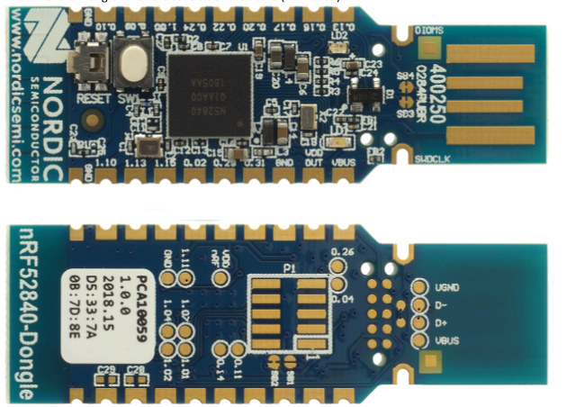
nRF52840 PCA10059
More information about the board can be found at the nRF52840 Dongle website [1]. The Nordic Semiconductor Infocenter [2] contains the processor’s information and the datasheet.
Hardware
The nrf52840_pca10059 has two external oscillators. The frequency of
the slow clock is 32.768 kHz. The frequency of the main clock
is 32 MHz.
Supported Features
The nrf52840_pca10059 board configuration supports the following
hardware features:
| Interface | Controller | Driver/Component |
|---|---|---|
| NVIC | on-chip | nested vectored interrupt controller |
| RTC | on-chip | system clock |
| GPIO | on-chip | gpio |
| FLASH | on-chip | flash |
| RADIO | on-chip | Bluetooth |
Other hardware features are not supported by the Zephyr kernel. See nRF52840 Dongle website [1] and Nordic Semiconductor Infocenter [2] for a complete list of nRF52840 PCA10059 Development Kit board hardware features.
Programming and Debugging
Applications for the nrf52840_pca10059 board configuration can be
built in the usual way (see Build an Application for more details);
however, an external debugger IC is necessary to program the device,
and the standard debugging targets are not currently available.
Flashing
Flashing Zephyr onto the nrf52840_pca10059 board requires an external
J-Link programmer. The programmer is attached to the SWD header on the back
side of the board.
Follow the instructions in the Nordic nRF5x Segger J-Link page to install and configure all the necessary software. Further information can be found in Flashing. Then build and flash applications as usual (see Build an Application and Run an Application for more details).
Here is an example for the Blinky Application application.
# On Linux/macOS
cd $ZEPHYR_BASE/samples/basic/blinky
mkdir build && cd build

# On Windows
cd %ZEPHYR_BASE%\samples\basic\blinky
mkdir build & cd build


# Use cmake to configure a Ninja-based build system:
cmake -GNinja -DBOARD=nrf52840_pca10059 ..

# Now run ninja on the generated build system:
ninja
ninja flash
Observe the LED on the board blinking.
Debugging
The nrf52840_pca10059 board does not have an on-board J-Link debug IC
as some nRF5x development boards, however, instructions from the
Nordic nRF5x Segger J-Link page also apply to this board, with the additional step
of connecting an external debugger.
Testing the LEDs and buttons on the nRF52840 PCA10059
There are 2 samples that allow you to test that the buttons (switches) and LEDs on the board are working properly with Zephyr:
You can build and program the examples to make sure Zephyr is running correctly on
your board. The button and LED definitions can be found in boards/arm/nrf52840_pca10059/board.h.