NXP FRDM-KW41Z
Overview
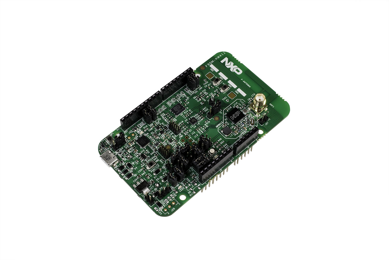
The FRDM-KW41Z is a development kit enabled by the Kinetis® W series KW41Z/31Z/21Z (KW41Z) family built on ARM® Cortex®-M0+ processor with integrated 2.4 GHz transceiver supporting Bluetooth® Smart/Bluetooth® Low Energy (BLE) v4.2, Generic FSK, IEEE® 802.15.4 and Thread.
The FRDM-KW41Z kit contains two Freedom boards that can be used as a development board or a shield to connect to a host processor. The FRDM-KW41Z is form-factor compatible with the Arduino™ R3 pin layout for more expansion options.
The FRDM-KW41Z highly-sensitive, optimized 2.4 GHz radio features a PCB F-antenna which can be bypassed to test via SMA connection, multiple power supply options, push/capacitive touch buttons, switches, LEDs and integrated sensors.
Hardware
- Can be configured as Host or Shield for connection to Host Processor
- Supports all DC-DC configurations (Buck, Boost, Bypass)
- PCB inverted F-type antenna
- SMA RF Connector
- RF regulatory certified
- Serial Flash for OTA firmware upgrades
- On board NXP FXOS8700CQ digital sensor, 3D Accelerometer ( ±2g/ ±4g/ ±8g) + 3D Magnetometer
- OpenSDA and JTAG debug
For more information about the KW41Z SoC and FRDM-KW41Z board:
- KW41Z Website
- KW41Z Datasheet
- KW41Z Reference Manual
- FRDM-KW41Z Website
- FRDM-KW41Z User Guide
- FRDM-KW41Z Schematics
Supported Features
The frdm_kw41z board configuration supports the following hardware features:
| Interface | Controller | Driver/Component |
|---|---|---|
| NVIC | on-chip | nested vector interrupt controller |
| SYSTICK | on-chip | systick |
| PINMUX | on-chip | pinmux |
| GPIO | on-chip | gpio |
| I2C | on-chip | i2c |
| SPI | on-chip | spi |
| ADC | on-chip | adc |
| UART | on-chip | serial port-polling; serial port-interrupt |
| FLASH | on-chip | soc flash |
| SENSOR | off-chip | fxos8700 polling: fxos8700 trigger |
The default configuration can be found in the defconfig file:
boards/arm/frdm_kw41z/frdm_kw41z_defconfig
Other hardware features are not currently supported by the port.
Connections and IOs
The KW41Z SoC has three pairs of pinmux/gpio controllers, but only two are currently enabled (PORTA/GPIOA and PORTC/GPIOC) for the FRDM-KW41Z board.
| Name | Function | Usage |
|---|---|---|
| PTC1 | GPIO | Red LED / FXOS8700 INT1 |
| PTA19 | GPIO | Green LED |
| PTA18 | GPIO | Blue LED |
| PTB2 | ADC | ADC0 channel 3 |
| PTC2 | I2C1_SCL | I2C / FXOS8700 |
| PTC3 | I2C1_SDA | I2C / FXOS8700 |
| PTC4 | GPIO | SW3 |
| PTC5 | GPIO | SW4 |
| PTC6 | LPUART0_RX | UART Console |
| PTC7 | LPUART0_TX | UART Console |
| PTC16 | SPI0_SCK | SPI |
| PTC17 | SPI0_SOUT | SPI |
| PTC18 | SPI0_SIN | SPI |
| PTC19 | SPI0_PCS0 | SPI |
System Clock
The KW41Z SoC is configured to use the 32 MHz external oscillator on the board with the on-chip FLL to generate a 40 MHz system clock.
Serial Port
The KW41Z SoC has one UART, which is used for the console.
Programming and Debugging
The FRDM-KW41Z includes the NXP OpenSDA serial and debug adapter built into the board to provide debugging, flash programming, and serial communication over USB.
To use the pyOCD tools with OpenSDA, follow the instructions in the
pyOCD page using the DAPLink FRDM-KW41Z Firmware. The
pyOCD tools are not the default for this board, therefore it is necessary to
set OPENSDA_FW=daplink explicitly when using the default flash and debug
mechanisms.
Note
pyOCD added support for KW41Z after support for this board was added to Zephyr, so you may need to build pyOCD from source based on the current master branch (f21d43d).
To use the Segger J-Link tools with OpenSDA, follow the instructions in the
Segger J-Link page using the Segger J-Link OpenSDA V2.1 Firmware.
The Segger J-Link tools are the default for this board, therefore it is not
necessary to set OPENSDA_FW=jlink explicitly in the environment before
programming and debugging.
With these mechanisms, applications for the frdm_kw41z board
configuration can be built and debugged in the usual way (see
Build an Application and Run an Application for more
details).
Flashing
The Segger J-Link firmware does not support command line flashing, therefore
the usual flash build system target is not supported.
Debugging
This example uses the Hello World sample with the Segger J-Link tools. Run the following to build your Zephyr application, invoke the J-Link GDB server, attach a GDB client, and program your Zephyr application to flash. It will leave you at a gdb prompt.
# On Linux/macOS
cd $ZEPHYR_BASE/samples/hello_world
mkdir build && cd build

# On Windows
cd %ZEPHYR_BASE%\samples\hello_world
mkdir build & cd build


# Use cmake to configure a Ninja-based build system:
cmake -GNinja -DBOARD=frdm_kw41z ..

# Now run ninja on the generated build system:
ninja debug