ST STM32F723E Discovery
Overview
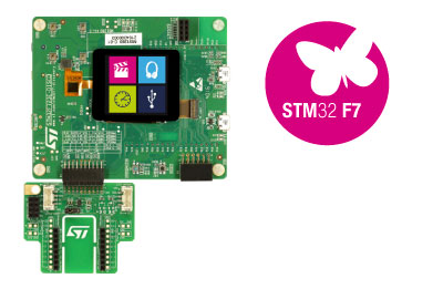
The discovery kit enables a wide diversity of applications taking benefit from audio, multi-sensor support, graphics, security, security, video, and high-speed connectivity features. Important board features include:
- STM32F723IEK6 microcontroller featuring 512 Kbytes of Flash memory and 256+16+4 Kbytes of RAM, in BGA176 package
- On-board ST-LINK/V2-1 supporting USB re-enumeration capability
- TFT LCD 240x240 pixels with touch panel
- SAI audio codec
- Audio line in and line out jack
- Stereo speaker outputs
- Four ST MEMS microphones
- Two pushbuttons (user and reset)
- 512-Mbit Quad-SPI Flash memory
- 8-Mbit external PSRAM
- USB OTG HS with Micro-AB connectors
- USB OTG FS with Micro-AB connectors
More information about the board can be found at the 32F723E-DISCO website.
Hardware
The STM32F723E Discovery kit provides the following hardware components:
- STM32F723IEK6 in BGA176 package
- ARM® 32-bit Cortex® -M7 CPU with FPU
- 216 MHz max CPU frequency
- VDD from 1.8 V to 3.6 V
- 1 MB Flash
- 256+16+4 KB SRAM including 64KB of tightly coupled memory
- GPIO with external interrupt capability
- 3x12-bit ADC with 24 channels
- 2x12-bit D/A converters
- RTC
- Advanced-control Timer (2)
- General Purpose Timers (13)
- Watchdog Timers (2)
- USART/UART (8)
- I2C (3)
- SPI (5)
- 2xSAI (serial audio interface)
- SDIO (2)
- CAN
- USB 2.0 OTG FS with on-chip PHY
- USB 2.0 OTG HS/FS with dedicated DMA, on-chip full-speed PHY and on-chip hi-speed PHY
- CRC calculation unit
- True random number generator
- DMA Controller
More information about STM32F723IEK6 can be found here:
Supported Features
The Zephyr stm32f723e_disco board configuration supports the following hardware features:
| Interface | Controller | Driver/Component |
|---|---|---|
| NVIC | on-chip | nested vector interrupt controller |
| UART | on-chip | serial port-polling; serial port-interrupt |
| PINMUX | on-chip | pinmux |
| GPIO | on-chip | gpio |
| I2C | on-chip | i2c |
| USB | on-chip | USB device |
Other hardware features are not yet supported on Zephyr porting.
The default configuration can be found in the defconfig file:
boards/arm/stm32f723e_disco/stm32f723e_disco_defconfig
Pin Mapping
STM32F723E Discovery kit has 7 GPIO controllers. These controllers are responsible for pin muxing, input/output, pull-up, etc.
For mode details please refer to 32F723E-DISCO board User Manual.
Default Zephyr Peripheral Mapping:
- I2C1_SCL: PB8
- I2C1_SDA: PB9
- I2C2_SCL: PH4
- I2C2_SDA: PH5
- I2C3_SCL: PA8
- I2C3_SDA: PH8
- LD1 : PA5
- LD5 : PA7
- LD6 : PB1
- OTG_FS_DM : PA11
- OTG_FS_DP : PA12
- UART_2_TX : PA2
- UART_2_RX : PA3
- UART_6_TX : PC6
- UART_6_RX : PC7
System Clock
The STM32F723E System Clock can be driven by an internal or external oscillator, as well as by the main PLL clock. By default, the System clock is driven by the PLL clock at 216MHz, driven by a 25MHz high speed external clock.
Serial Port
The STM32F723E Discovery kit has up to 8 UARTs. The Zephyr console output is assigned to UART6 which connected to the onboard ST-LINK/V2 Virtual COM port interface. Default communication settings are 115200 8N1.
Programming and Debugging
Applications for the stm32f723e_disco board configuration can be built and
flashed in the usual way (see Build an Application and
Run an Application for more details).
Flashing
STM32F723E Discovery kit includes an ST-LINK/V2 embedded debug tool interface. This interface is supported by the openocd version included in the Zephyr SDK.
Flashing an application to STM32F723E-DISCO
First, connect the STM32F723E Discovery kit to your host computer using the USB port to prepare it for flashing. Then build and flash your application.
Here is an example for the Hello World application.
# On Linux/macOS
cd $ZEPHYR_BASE/samples/hello_world
mkdir build && cd build

# On Windows
cd %ZEPHYR_BASE%\samples\hello_world
mkdir build & cd build


# Use cmake to configure a Ninja-based build system:
cmake -GNinja -DBOARD=stm32f723e_disco ..

# Now run ninja on the generated build system:
ninja
ninja flash
Run a serial host program to connect with your board:
$ minicom -D /dev/ttyACM0
You should see the following message on the console:
Hello World! arm
Debugging
You can debug an application in the usual way. Here is an example for the Hello World application.
# On Linux/macOS
cd $ZEPHYR_BASE/samples/hello_world
mkdir build && cd build

# On Windows
cd %ZEPHYR_BASE%\samples\hello_world
mkdir build & cd build


# Use cmake to configure a Ninja-based build system:
cmake -GNinja -DBOARD=stm32f723e_disco ..

# Now run ninja on the generated build system:
ninja debug