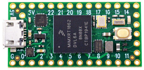
Teensy 4.0
PJRC TEENSY 4
Overview
The Teensy is a complete USB-based microcontroller development system, in a very small footprint, capable of implementing many types of projects. All programming is done via the USB port.
Hardware
MIMXRT1062DVL6A MCU (600 MHz, 1024 KB on-chip memory)
16 Mbit QSPI Flash
User LED
USB 2.0 host connector
See the Teensy 4.0 Website [1] for a complete hardware description.
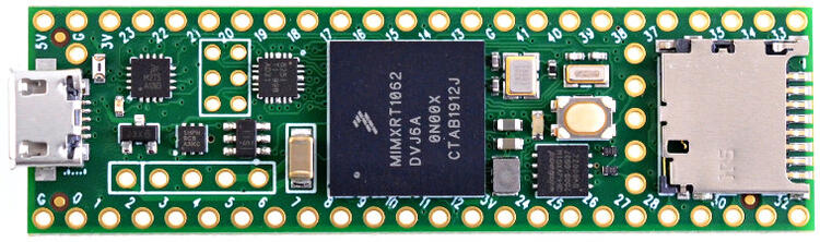
MIMXRT1062DVJ6A MCU (600 MHz, 1024 KB on-chip memory)
64 Mbit QSPI Flash
User LED
USB 2.0 host connector
USB 2.0 OTG connector
10/100 Mbit/s Ethernet transceiver
TF socket for SD card
To connect an Ethernet cable, additional Teensy 4.1 Ethernet Kit [3] is required.
See the Teensy 4.1 Website [2] for a complete hardware description.
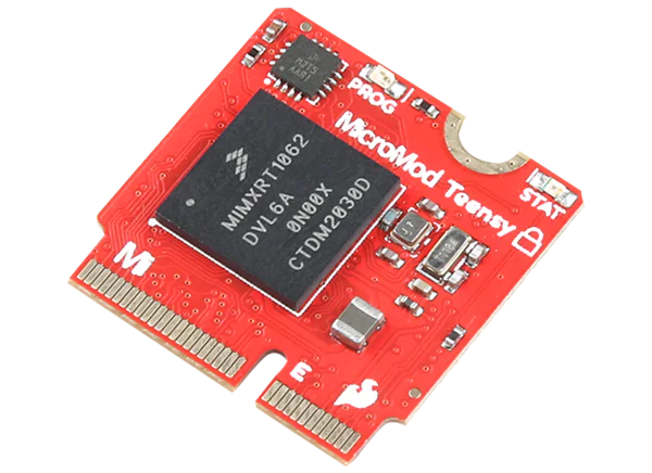
MIMXRT1062DVJ6A MCU (600 MHz, 1024 KB on-chip memory)
128 Mbit QSPI Flash
User LED
USB 2.0 host connector
USB 2.0 OTG connector
TF socket for SD card
See the Teensy Micromod Website [4] for a complete hardware description.
For more information, check the i.MX RT1060 Datasheet [5].
Supported Features
The teensy40 board supports the hardware features listed below.
- on-chip / on-board
- Feature integrated in the SoC / present on the board.
- 2 / 2
-
Number of instances that are enabled / disabled.
Click on the label to see the first instance of this feature in the board/SoC DTS files. -
vnd,foo -
Compatible string for the Devicetree binding matching the feature.
Click on the link to view the binding documentation.
teensy40/mimxrt1062 target
On-target memory for this board target: 256 KiB of RAM, 2 MiB of Flash.
Type |
Location |
Description |
Compatible |
|---|---|---|---|
CPU |
on-chip |
ARM Cortex-M7 CPU1 |
|
ADC |
on-chip |
NXP MCUA 12B1MSPS SAR ADC2 |
|
ARM architecture |
on-chip |
MCUX XBAR (Crossbar)3 |
|
CAN |
on-chip |
||
on-chip |
NXP FlexCAN CANFD controller1 |
||
Clock control |
on-chip |
i.MX CCM (Clock Controller Module) IP node1 |
|
on-chip |
Generic fixed factor clock provider3 |
||
on-chip |
i.MX CCM Fractional PLL1 |
||
on-chip |
i.MX ANATOP (Analog Clock Controller Module) IP node1 |
||
on-chip |
Generic fixed-rate clock provider4 |
||
Counter |
on-chip |
NXP MCUX General-Purpose Timer (GPT)1 |
|
on-chip |
NXP MCUX Quad Timer (QTMR)4 |
||
on-chip |
NXP MCUX Quad Timer Channel16 |
||
on-chip |
NXP SNVS LP/HP Realtime Counter1 |
||
on-chip |
NXP Periodic Interrupt Timer (PIT)1 |
||
on-chip |
Child node for the Periodic Interrupt Timer node, intended for an individual timer channel4 |
||
Cryptographic accelerator |
on-chip |
NXP Data Co-Processor (DCP) Crypto accelerator1 |
|
Debug |
on-chip |
ARMv7 instrumentation trace macrocell1 |
|
Display |
on-chip |
NXP i.MX eLCDIF (Enhanced LCD Interface) controller1 |
|
DMA |
on-chip |
NXP MCUX EDMA controller1 |
|
on-chip |
NXP PXP 2D DMA engine1 |
||
Ethernet |
on-chip |
NXP ENET IP Module2 |
|
on-chip |
NXP ENET MAC/L2 Device2 |
||
on-chip |
NXP ENET MDIO Features2 |
||
on-chip |
NXP ENET PTP (Precision Time Protocol) Clock2 |
||
GPIO & Headers |
on-chip |
i.MX GPIO9 |
|
I2C |
on-chip |
NXP LPI2C controller4 |
|
I2S |
on-chip |
NXP mcux SAI-I2S controller3 |
|
Interrupt controller |
on-chip |
ARMv7-M NVIC (Nested Vectored Interrupt Controller)1 |
|
LED |
on-board |
Group of GPIO-controlled LEDs1 |
|
Memory controller |
on-chip |
NXP FlexRAM on-chip RAM controller1 |
|
on-chip |
NXP Smart External Memory Controller (SEMC)1 |
||
on-chip |
NXP i.MX SNVS Low-Power General Purpose Registers used as battery-backed RAM1 |
||
Miscellaneous |
on-chip |
NXP FlexIO controller3 |
|
MMU / MPU |
on-chip |
ARMv7-M Memory Protection Unit (MPU)1 |
|
MTD |
on-board |
NXP FlexSPI NOR1 |
|
on-board |
Flash node1 |
||
OTP memory |
on-chip |
NXP OCOTP1 |
|
Pin control |
on-chip |
This compatible binding should be applied to the device’s iomuxc DTS node1 |
|
on-chip |
The node has the ‘pinctrl’ node label set in MCUX RT SoC’s devicetree1 |
||
on-chip |
i.MX IOMUXC1 |
||
PWM |
on-chip |
NXP eFLEX PWM module with mcux-pwm submodules4 |
|
on-chip |
NXP MCUX PWM16 |
||
RNG |
on-chip |
Kinetis TRNG (True Random Number Generator)1 |
|
SDHC |
on-chip |
NXP imx USDHC controller2 |
|
Sensors |
on-chip |
NXP MCUX QDEC4 |
|
on-chip |
NXP on-die temperature monitor1 |
||
Serial controller |
on-chip |
||
SPI |
on-chip |
||
on-chip |
NXP LPSPI controller4 |
||
Timer |
on-chip |
ARMv7-M System Tick1 |
|
on-chip |
NXP MCUX General-Purpose HW Timer (GPT)1 |
||
USB |
on-chip |
||
on-chip |
NXP EHCI USB host controller2 |
||
on-chip |
NXP USB High Speed PHY2 |
||
Video |
on-chip |
NXP MCUX CMOS sensor interface1 |
|
Watchdog |
on-chip |
imxRT watchdog2 |
Connections and IOs
Pin mappings from Teensy to MIMXRT1062 SoC.
Pin |
Pad ID |
Usage |
|---|---|---|
0 |
AD_B0_03 |
GPIO1_3 / UART6_RX / CAN2_RX |
1 |
AD_B0_02 |
GPIO1_2 / UART6_TX / CAN2_TX |
2 |
EMC_04 |
GPIO4_4 |
3 |
EMC_05 |
GPIO4_5 |
4 |
EMC_06 |
GPIO4_6 |
5 |
EMC_08 |
GPIO4_8 |
6 |
B0_10 |
GPIO2_10 |
7 |
B1_01 |
GPIO2_17 / UART4_RX |
8 |
B1_00 |
GPIO2_16 / UART4_TX |
9 |
B0_11 |
GPIO2_11 |
10 |
B0_00 |
GPIO2_0 |
11 |
B0_02 |
GPIO2_2 |
12 |
B0_01 |
GPIO2_1 |
13 |
B0_03 |
GPIO2_3 / LED |
14 |
AD_B1_02 |
GPIO1_18 / UART2_TX |
15 |
AD_B1_03 |
GPIO1_19 / UART2_RX |
16 |
AD_B1_07 |
GPIO1_23 / UART3_RX / I2C3_SCL |
17 |
AD_B1_06 |
GPIO1_22 / UART3_TX / I2C3_SDA |
18 |
AD_B1_01 |
GPIO1_17 / I2C1_SDA |
19 |
AD_B1_00 |
GPIO1_16 / I2C1_SCL |
20 |
AD_B1_10 |
GPIO1_26 / UART8_TX |
21 |
AD_B1_11 |
GPIO1_27 / UART8_RX |
22 |
AD_B1_08 |
GPIO1_24 / CAN1_TX |
23 |
AD_B1_09 |
GPIO1_25 / CAN1_RX |
24 |
AD_B0_12 |
GPIO1_12 / UART1_TX / I2C4_SCL |
25 |
AD_B0_13 |
GPIO1_13 / UART1_RX / I2C4_SDA |
26 |
AD_B1_14 |
GPIO1_30 / SPI3_MOSI |
27 |
AD_B1_15 |
GPIO1_31 / SPI3_SCK |
28 |
EMC_32 |
GPIO3_18 / UART7_RX |
29 |
EMC_31 |
GPIO4_31 / UART7_TX |
30 |
EMC_37 |
GPIO3_23 / CAN3_RX |
31 |
EMC_36 |
GPIO3_22 / CAN3_TX |
32 |
B0_12 |
GPIO2_12 |
33 |
EMC_07 |
GPIO4_7 |
Only Teensy 4.0 and Teensy Micromod:
34 |
SD_B0_03 |
GPIO3_15 |
35 |
SD_B0_02 |
GPIO3_14 |
36 |
SD_B0_01 |
GPIO3_13 |
37 |
SD_B0_00 |
GPIO3_12 |
38 |
SD_B0_05 |
GPIO3_17 |
39 |
SD_B0_04 |
GPIO3_16 |
Only Teensy Micromod
40 |
B0_04 |
GPIO2_4 / I2C2 SCL |
41 |
B0_05 |
GPIO2_5 / I2C2 SDA |
42 |
B0_06 |
GPIO2_6 |
43 |
B0_07 |
GPIO2_7 |
44 |
B0_08 |
GPIO2_8 / UART3 TX |
45 |
B0_09 |
GPIO2_9 / UART3 RX |
Only Teensy 4.1:
34 |
B1_13 |
GPIO2_29 / UART5_RX |
35 |
B1_12 |
GPIO2_28 / UART5_TX |
36 |
B1_02 |
GPIO2_18 |
37 |
B1_03 |
GPIO2_19 |
38 |
AD_B1_12 |
GPIO1_28 / SPI3_CS |
39 |
AD_B1_13 |
GPIO1_29 / SPI3_MISO |
40 |
AD_B1_04 |
GPIO1_20 |
41 |
AD_B1_05 |
GPIO1_21 / UART3_RX |
Pin mappings from Teensy Micromod pins to MIMXRT1062 SoC.
Teensy Micromod only:
MMOD |
MMC |
Pin |
Pad ID |
Usage |
|---|---|---|---|---|
8 |
16 |
27 |
AD_B1_15 |
<gpio1 31> / SPI3_SCK |
10 |
2 |
4 |
EMC_06 |
<gpio4 6> |
12 |
18 |
AD_B1_01 |
<gpio1 17> / I2C1_SDA |
|
14 |
19 |
AD_B1_00 |
<gpio1 16> / I2C1_SCL |
|
16 |
4 |
29 |
EMC_31 |
<gpio4 31> / UART7_TX |
17 |
1 |
AD_B0_02 |
<gpio1 2> / UART6_TX / CAN2_TX |
|
18 |
3 |
5 |
EMC_08 |
<gpio4 8> |
19 |
0 |
AD_B0_03 |
<gpio1 3> / UART6_RX / CAN2_RX |
|
20 |
16 |
AD_B1_07 |
<gpio1 23> / UART3_RX / I2C3_SCL |
|
22 |
17 |
AD_B1_06 |
<gpio1 22> / UART3_TX / I2C3_SDA |
|
32 |
3 |
EMC_05 |
<gpio4 5> |
|
34 |
0 |
14 |
AD_B1_02 |
<gpio1 18> / UART2_TX |
38 |
1 |
15 |
AD_B1_03 |
<gpio1 19> / UART2_RX |
4 |
28 |
EMC_32 |
<gpio3 18> / UART7_RX |
|
40 |
5 |
40 |
B0_04 |
<gpio2 04> / I2C2 SCL |
41 |
30 |
EMC_37 |
<gpio3 23> / CAN3_RX |
|
42 |
6 |
41 |
B0_05 |
<gpio2 05> / I2C2 SDA |
43 |
31 |
EMC_36 |
<gpio3 22> / CAN3_TX |
|
44 |
7 |
42 |
B0_06 |
<gpio2 06> |
46 |
8 |
43 |
B0_07 |
<gpio2 07> |
47 |
2 |
EMC_04 |
<gpio4 4> |
|
48 |
9 |
44 |
B0_08 |
<gpio2 08> / UART3 TX |
49 |
22 |
AD_B1_08 |
<gpio1 24> / CAN1_TX |
|
50 |
21 |
AD_B1_11 |
<gpio1 27> / UART8_RX |
|
51 |
25 |
AD_B0_13 |
<gpio1 13> / UART1_RX / I2C4_SDA |
|
52 |
20 |
AD_B1_10 |
<gpio1 26> / UART8_TX |
|
53 |
24 |
AD_B0_12 |
<gpio1 12> / UART1_TX / I2C4_SCL |
|
54 |
8 |
B1_00 |
<gpio2 16> / UART4_TX |
|
55 |
17 |
10 |
B0_00 |
<gpio2 0> |
56 |
7 |
B1_01 |
<gpio2 17> / UART4_RX |
|
57 |
13 |
B0_03 |
<gpio2 3> / LED |
|
58 |
23 |
AD_B1_09 |
<gpio1 25> / CAN1_RX |
|
59 |
11 |
B0_02 |
<gpio2 2> |
|
60 |
36 |
SD_B0_01 |
<gpio3 13> |
|
61 |
12 |
B0_01 |
<gpio2 1> |
|
62 |
37 |
SD_B0_00 |
<gpio3 12> |
|
63 |
15 |
33 |
EMC_07 |
<gpio4 7> |
64 |
35 |
SD_B0_02 |
<gpio3 14> |
|
65 |
14 |
32 |
B0_12 |
<gpio2 12> |
66 |
34 |
SD_B0_03 |
<gpio3 15> |
|
67 |
13 |
26 |
AD_B1_14 |
<gpio1 30> / SPI3_MOSI |
68 |
38 |
SD_B0_05 |
<gpio3 16> |
|
69 |
12 |
9 |
B0_11 |
<gpio2 11> |
70 |
39 |
SD_B0_04 |
<gpio3 17> |
|
71 |
11 |
6 |
B0_10 |
<gpio2 10> |
73 |
10 |
45 |
B0_09 |
<gpio2 09> / UART3 RX |
MMOD = Physical Micromod pin number MMC = Zephyr micromod_header connector pin number Pin = Arduino Pin number Pad ID = MIMXRT1062 pad id Usage = Some usages of the pin
Programming and Debugging
Flashing
The Teensy 4.0 and Teensy 4.1 and Micromod ship with a dedicated bootloader chip, which supports flashing using USB. This allows easy flashing of new images, but does not support debugging the device.
Build the Zephyr kernel and the Blinky sample application.
west build -b teensy40 samples/basic/blinky
west build -b teensy41 samples/basic/blinky
west build -b teensymm samples/basic/blinky
Connect the board to your host computer using USB.
Tap the reset button to enter bootloader mode. Red LED blinks.
Flash the image.
west build -b teensy40 samples/basic/blinky
west flash
west build -b teensy41 samples/basic/blinky
west flash
west build -b teensymm samples/basic/blinky
west flash
You should see the orange LED blink.
Configuring a Console
By default console output is mapped to teensy pins 0 (RX1) and 1 (TX1). Connect a usb-to-serial adapter to use this serial console. Use the following settings with your serial terminal of choice (minicom, putty, etc.):
Speed: 115200
Data: 8 bits
Parity: None
Stop bits: 1
By mapping the console output to USB, a usb-to-serial adapter is no longer required. Utilizing the CDC-ACM Console Snippet (cdc-acm-console) and a config option will enable this feature.
If application code doesn´t enable USB device support, this must be done via Kconfig option.
CONFIG_USB_DEVICE_INITIALIZE_AT_BOOT=y
Build application including the snippet.
west build -b teensy41 -S cdc-acm-console samples/basic/blinky
west flash
After application startup a serial device named like
tty.usbmodem14203should appear on your host computer. You can use e.g.Serial Monitorplugin for VScode to monitor.