MicroMod board Processor
SparkFun MicroMod board Processor
Overview
MicroMod is a solderless, modular interface ecosystem that uses the M.2 standard to mix and match your choice of processor with specific Function Boards or stand-alone Carrier Boards. A MicroMod processor board is approximately 22x22 mm, and can insert into any MicroMod carrier board. More information can be found in the Micromod specification website [1].
All Micromod board targets support the following hardware features:
USB host mode compliant to 2.0 specification
GPIO
2 UART
2 I2C
2 SPI
2 ADC
2 PWM
Watchdog Timer (WDT)
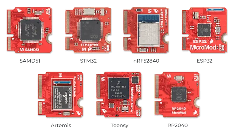
Sparkfun Micromod board (Credit: https://www.sparkfun.com)
Zephyr currently supports the following SoCs:
micromod/nrf52840
SparkFun MicroMod nRF52840 board Processor
Overview
The micromod/nrf52840 board target features the nRF52840 SoC
from Nordic Semiconductor, the SparkFun MicroMod nRF52840 Processor offers
a powerful combination of ARM Cortex-M4 CPU and 2.4 GHz Bluetooth transceiver
in the MicroMod form-factor. More information can be found in
the Micromod nRF52840 guide [3].
Hardware
The micromod/nrf52840 board target supports the following
hardware features:
ARM Cortex-M4 CPU with floating point unit (FPU)
1MB internal Flash
256kB internal RAM
Integrated 2.4GHz radio with support for Bluetooth Low Energy (BLE) and ieee802154
USB 2.0 full speed (12 Mbps) controller
QSPI with 128Mb flash memory
ARM TrustZone Cryptocell 310 security subsystem
USB host mode compliant to 2.0 specification
GPIO
2 UART
2 I2C
2 SPI
2 ADC
2 PWM
Watchdog Timer (WDT)
Supported Features
The micromod board supports the hardware features listed below.
- on-chip / on-board
- Feature integrated in the SoC / present on the board.
- 2 / 2
-
Number of instances that are enabled / disabled.
Click on the label to see the first instance of this feature in the board/SoC DTS files. -
vnd,foo -
Compatible string for the Devicetree binding matching the feature.
Click on the link to view the binding documentation.
micromod/nrf52840 target
On-target memory for this board target: 256 KiB of RAM, 1 MiB of Flash.
Type |
Location |
Description |
Compatible |
|---|---|---|---|
CPU |
on-chip |
ARM Cortex-M4F CPU1 |
|
ADC |
on-chip |
Nordic Semiconductor nRF family SAADC node1 |
|
ARM architecture |
on-chip |
Nordic UICR (User Information Configuration Registers)1 |
|
on-chip |
Nordic EGU (Event Generator Unit)6 |
||
on-chip |
Nordic nRF family ACL (Access Control List)1 |
||
on-chip |
Nordic nRF family MWU (Memory Watch Unit)1 |
||
Audio |
on-chip |
Nordic PDM (Pulse Density Modulation interface)1 |
|
Clock control |
on-chip |
Nordic nRF clock control node1 |
|
on-chip |
Nordic nRF high-frequency crystal oscillator (nRF52 series)1 |
||
Comparator |
on-chip |
Nordic nRF COMP (analog COMParator)1 |
|
Counter |
on-chip |
Nordic nRF timer node5 |
|
Cryptographic accelerator |
on-chip |
Nordic ECB (AES electronic codebook mode encryption)1 |
|
on-chip |
Nordic nRF family CCM (AES CCM mode encryption)1 |
||
on-chip |
ARM TrustZone CryptoCell 3101 |
||
Debug |
on-chip |
ARMv7 instrumentation trace macrocell1 |
|
Flash controller |
on-chip |
Nordic NVMC (Non-Volatile Memory Controller)1 |
|
on-chip |
Properties defining the interface for the Nordic QSPI peripheral1 |
||
GPIO & Headers |
on-chip |
NRF5 GPIOTE1 |
|
on-chip |
NRF5 GPIO2 |
||
on-board |
GPIO pins exposed on micromod headers1 |
||
I2C |
on-chip |
Nordic nRF family TWI (TWI master)2 |
|
I2S |
on-chip |
Nordic I2S (Inter-IC sound interface)1 |
|
IEEE 802.15.4 |
on-chip |
Nordic nRF IEEE 802.15.4 node1 |
|
Interrupt controller |
on-chip |
ARMv7-M NVIC (Nested Vectored Interrupt Controller)1 |
|
LED |
on-board |
Group of GPIO-controlled LEDs1 |
|
Miscellaneous |
on-chip |
Nordic FICR (Factory Information Configuration Registers)1 |
|
on-chip |
Nordic nRF family PPI (Programmable Peripheral Interconnect)1 |
||
MTD |
on-chip |
Flash node1 |
|
on-board |
QSPI NOR flash supporting the JEDEC CFI interface1 |
||
Networking |
on-chip |
Nordic nRF family RADIO peripheral1 |
|
on-chip |
Nordic nRF family NFCT (Near Field Communication Tag)1 |
||
Pin control |
on-chip |
Nordic nRF family Pin Controller1 |
|
Power management |
on-chip |
Nordic nRF power control node1 |
|
PWM |
on-chip |
nRF PWM4 |
|
on-chip |
nRFx S/W PWM1 |
||
Regulator |
on-chip |
Nordic nRF5X regulator (fixed stage of the core supply)1 |
|
on-chip |
Nordic nRF52X regulator (high voltage stage of the main supply)1 |
||
Retained memory |
on-chip |
Nordic GPREGRET (General Purpose Register Retention) device2 |
|
RNG |
on-chip |
Nordic nRF family RNG (Random Number Generator)1 |
|
RTC |
on-chip |
Nordic nRF RTC (Real-Time Counter)3 |
|
Sensors |
on-chip |
Nordic nRF family TEMP node1 |
|
on-chip |
Nordic nRF quadrature decoder (QDEC) node1 |
||
Serial controller |
on-chip |
Nordic nRF family UARTE (UART with EasyDMA)2 |
|
SPI |
on-chip |
Nordic nRF family SPIM (SPI master with EasyDMA)3 |
|
on-chip |
Nordic nRF family SPI (SPI master)1 |
||
SRAM |
on-chip |
Generic on-chip SRAM1 |
|
Timer |
on-chip |
ARMv7-M System Tick1 |
|
USB |
on-chip |
Nordic nRF52 USB device controller1 |
|
Watchdog |
on-chip |
Nordic nRF family WDT (Watchdog Timer)1 |
Connections and IOs
LED
Led0 (blue) = P0.13
Micromod header
micromod_1_uart = uart0
micromod_2_uart = uart1
micromod_0_i2c = i2c0
micromod_1_i2c = i2c1
micromod_0_spi = spi2
micromod_header compatible with
sparkfun,micromod-gpio
Programming and Debugging
Applications for the micromod/nrf52840 board target can be
built, flashed, and debugged in the usual way. See
Building an Application and Run an Application for more details on
building and running.
Flashing
Follow the instructions in the Nordic nRF5x Segger J-Link page to install and configure all the necessary software. Further information can be found in Flashing. Then build and flash applications as usual (see Building an Application and Run an Application for more details).
The flashing tool will depend on the carrier used along with the board. In the case of Sparkfun asset tracking carrier [2], it is possible to use the SWD interface along with a J-Link.
Here is an example for the Hello World application.
First, run your favorite terminal program to listen for output.
$ minicom -D <tty_device> -b 115200
Replace <tty_device> with the port where the board nRF52840 DK
can be found. For example, under Linux, /dev/ttyACM0.
Then build and flash the application in the usual way.
# From the root of the zephyr repository
west build -b micromod/nrf52840 samples/hello_world
west flash
Debugging
Refer to the Nordic nRF5x Segger J-Link page to learn about debugging Nordic boards with a Segger IC.
In case of using a Nordic Segger Jlink, it is possible to configure the app to use Segger Real Time Transfer (RTT) for debugging. In this case, build your app with the RTT snippet.
Testing the on-board LED
There is a sample that allow you to test the LED on the board is working properly with Zephyr:
You can build and flash the example to make sure Zephyr is running correctly on your board. The button and LED definitions can be found in boards/sparkfun/micromod/micromod_nrf52840.dts.
Testing the 128Mb qspi memory flash
The micromod/nrf52840 board target has a built-in NOR flash memory connected
to the qspi interface. It can be tested with the samples/drivers/jesd216 app.
# From the root of the zephyr repository
west build -b micromod/nrf52840 samples/drivers/jesd216
west flash