ARM V2M MPS2 Armv6-m (AN383)
Overview
Currently mps2/an383 is the only mps2 Armv6-m based board target supported in Zephyr.
It provides support for the ARM Cortex-M0+ (AN383) CPU and the following devices:
Nested Vectored Interrupt Controller (NVIC)
System Tick System Clock (SYSTICK)
Cortex-M System Design Kit UART
In addition to enabling actual hardware usage, this board target can also use FVP. to emulate the AN383 platform running on the MPS2+.
More information about the board can be found at the V2M MPS2 Website.
The Application Note AN383 can be found at Application Note AN383.
Note
This board target makes no claims about its suitability for use with actual MPS2 hardware systems using AN383, or any other hardware system. It has been tested on FVP.
Hardware
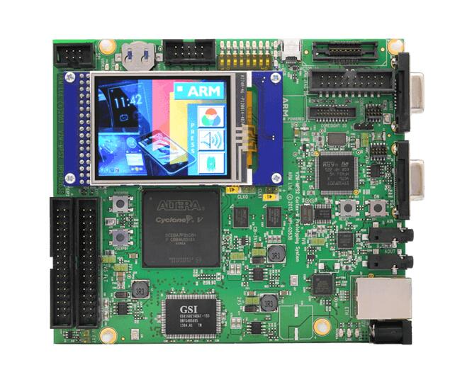
ARM V2M MPS2 AN383 provides the following hardware components:
ARM Cortex-M0+
ARM IoT Subsystem for Cortex-M
Form factor: 140x120cm
ZBTSRAM: 8MB single cycle SRAM, 16MB PSRAM
Video: QSVGA touch screen panel, 4bit RGB VGA connector
Audio: Audio Codec
Debug:
ARM JTAG20 connector
ARM parallel trace connector (MICTOR38)
20 pin Cortex debug connector
10 pin Cortex debug connector
ILA connector for FPGA debug
Expansion
GPIO
SPI
Note
4 MB of flash memory (in ZBTSRAM 1, starting at address 0x00400000) and 4 MB of RAM (in ZBTSRAM 2 & 3, starting at address 0x20000000) are available.
Supported Features
Refer to V2M MPS2 for details.
Interrupt Controller
MPS2 is a Cortex-M0+ based SoC and has 6 fixed exceptions and 32 IRQs.
A Cortex-M0+ board uses vectored exceptions. This means each exception calls a handler directly from the vector table.
Handlers are provided for exceptions 1-3, 11, and 14-15. The table here MPS2 is a Cortex-M0+ based SoC and has 15 fixed exceptions and 45 IRQs.
Exc# |
Name |
Remarks |
Used by Zephyr Kernel |
|---|---|---|---|
1 |
Reset |
system initialization |
|
2 |
NMI |
system fatal error |
|
3 |
Hard fault |
system fatal error |
|
11 |
SVC |
system calls, kernel run-time exceptions, and IRQ offloading |
|
14 |
PendSV |
context switch |
|
15 |
SYSTICK |
optional |
system clock |
Pin Mapping
The ARM V2M MPS2 Board has 4 GPIO controllers. These controllers are responsible for pin muxing, input/output, pull-up, etc.
All GPIO controller pins are exposed via the following sequence of pin numbers:
Pins 0 - 15 are for GPIO 0
Pins 16 - 31 are for GPIO 1
Pins 32 - 47 are for GPIO 2
Pins 48 - 51 are for GPIO 3
Mapping from the ARM MPS2 Board pins to GPIO controllers:
D0 : EXT_0
D1 : EXT_4
D2 : EXT_2
D3 : EXT_3
D4 : EXT_1
D5 : EXT_6
D6 : EXT_7
D7 : EXT_8
D8 : EXT_9
D9 : EXT_10
D10 : EXT_12
D11 : EXT_13
D12 : EXT_14
D13 : EXT_11
D14 : EXT_15
D15 : EXT_5
D16 : EXT_16
D17 : EXT_17
D18 : EXT_18
D19 : EXT_19
D20 : EXT_20
D21 : EXT_21
D22 : EXT_22
D23 : EXT_23
D24 : EXT_24
D25 : EXT_25
D26 : EXT_26
D27 : EXT_30
D28 : EXT_28
D29 : EXT_29
D30 : EXT_27
D31 : EXT_32
D32 : EXT_33
D33 : EXT_34
D34 : EXT_35
D35 : EXT_36
D36 : EXT_38
D37 : EXT_39
D38 : EXT_40
D39 : EXT_44
D40 : EXT_41
D41 : EXT_31
D42 : EXT_37
D43 : EXT_42
D44 : EXT_43
D45 : EXT_45
D46 : EXT_46
D47 : EXT_47
D48 : EXT_48
D49 : EXT_49
D50 : EXT_50
D51 : EXT_51
Peripheral Mapping:
UART_3_RX : D0
UART_3_TX : D1
SPI_3_CS : D10
SPI_3_MOSI : D11
SPI_3_MISO : D12
SPI_3_SCLK : D13
I2C_3_SDA : D14
I2C_3_SCL : D15
UART_4_RX : D26
UART_4_TX : D30
SPI_4_CS : D36
SPI_4_MOSI : D37
SPI_4_MISO : D38
SPI_4_SCK : D39
I2C_4_SDA : D40
I2C_4_SCL : D41
For more details please refer to MPS2 Technical Reference Manual (TRM).
System Clock
The V2M MPS2 main clock is 24 MHz.
Serial Port
The V2M MPS2 processor has five UARTs. Both the UARTs have only two wires for RX/TX and no flow control (CTS/RTS) or FIFO. The Zephyr console output, by default, is utilizing UART0.
Programming and Debugging
Flashing
V2M MPS2 provides:
A USB connection to the host computer, which exposes a Mass Storage and an USB Serial Port.
A Serial Flash device, which implements the USB flash disk file storage.
A physical UART connection which is relayed over interface USB Serial port.
Flashing an application to V2M MPS2
Here is an example for the Hello World application.
# From the root of the zephyr repository
west build -b mps2/an383 samples/hello_world
Connect the V2M MPS2 to your host computer using the USB port and you should see a USB connection which exposes a Mass Storage and a USB Serial Port. Copy the generated zephyr.bin in the exposed drive. Reset the board and you should be able to see on the corresponding Serial Port the following message:
Hello World! arm
Running an applicatoin with FVP
Here is the same example for running with FVP.
Set the ARMFVP_BIN_PATH environment variable to the location of your FVP you have downloaded from here
export ARMFVP_BIN_PATH=/home/../FVP_MPS2/
Then build with the same command you would use normally, and run with west build -t run_armfvp.