ICE-V Wireless
Overview
The ICE-V Wireless is a combined ESP32-C3 and iCE40 FPGA board.
See the ICE-V Wireless Github Project [6] for details.
Hardware
This board combines an Espressif ESP32-C3-MINI-1 (which includes 4MB of flash in the module) with a Lattice iCE40UP5k-SG48 FPGA to allow WiFi and Bluetooth control of the FPGA. ESP32 and FPGA I/O is mostly uncommitted except for the pins used for SPI communication between ESP32 and FPGA. Several of the ESP32C3 GPIO pins are available for additional interfaces such as serial, ADC, I2C, etc.
For details on ESP32-C3 hardware please refer to the following resources:
For details on iCE40 hardware please refer to the following resources:
ESP32-C3 Features
ESP32-C3 is a single-core Wi-Fi and Bluetooth 5 (LE) microcontroller SoC, based on the open-source RISC-V architecture. It strikes the right balance of power, I/O capabilities and security, thus offering the optimal cost-effective solution for connected devices. The availability of Wi-Fi and Bluetooth 5 (LE) connectivity not only makes the device configuration easy, but it also facilitates a variety of use-cases based on dual connectivity.
The features include the following:
32-bit core RISC-V microcontroller with a maximum clock speed of 160 MHz
802.11b/g/n/
A Bluetooth LE subsystem that supports features of Bluetooth 5 and Bluetooth Mesh
384 KB ROM
400 KB SRAM (16 KB for cache)
8 KB SRAM in RTC
22 x programmable GPIOs
Various peripherals:
Full-speed USB Serial/JTAG controller
TWAI® compatible with CAN bus 2.0
General DMA controller (GDMA)
2x 12-bit SAR ADC with up to 6 channels
3x SPI
2x UART
1x I2S
1x I2C
2 x 54-bit general-purpose timers
3 x watchdog timers
1 x 52-bit system timer
Remote Control Peripheral (RMT)
LED PWM controller (LEDC) with up to 6 channels
Temperature sensor
Cryptographic hardware acceleration (RNG, ECC, RSA, SHA-2, AES)
For more information, check the ESP32-C3 Datasheet [1] or the ESP32-C3 Technical Reference Manual [2].
Supported Features
The icev_wireless board supports the hardware features listed below.
- on-chip / on-board
- Feature integrated in the SoC / present on the board.
- 2 / 2
-
Number of instances that are enabled / disabled.
Click on the label to see the first instance of this feature in the board/SoC DTS files. -
vnd,foo -
Compatible string for the Devicetree binding matching the feature.
Click on the link to view the binding documentation.
icev_wireless/esp32c3 target
On-target memory for this board target: 384 KiB of RAM, 4 MiB of Flash.
Type |
Location |
Description |
Compatible |
|---|---|---|---|
CPU |
on-chip |
Espressif RISC-V CPU1 |
|
ADC |
on-chip |
ESP32 ADC1 |
|
Bluetooth |
on-chip |
Bluetooth HCI for Espressif ESP321 |
|
CAN |
on-chip |
ESP32 Two-Wire Automotive Interface (TWAI)1 |
|
Clock control |
on-chip |
ESP32 Clock (Power & Clock Controller Module) Module1 |
|
Counter |
on-chip |
ESP32 Counter Driver based on RTC Main Timer1 |
|
on-chip |
ESP32 general-purpose timers2 |
||
on-chip |
ESP32 counters2 |
||
Cryptographic accelerator |
on-chip |
Espressif ESP32 SHA Hardware Accelerator1 |
|
on-chip |
Espressif ESP32 family AES Hardware Accelerator1 |
||
DMA |
on-chip |
ESP32 GDMA (General Direct Memory Access)1 |
|
Flash controller |
on-chip |
ESP32 flash controller1 |
|
GPIO & Headers |
on-chip |
ESP32 GPIO controller1 |
|
I2C |
on-chip |
ESP32 I2C1 |
|
I2S |
on-chip |
ESP32 I2S1 |
|
Input |
on-board |
Group of GPIO-bound input keys1 |
|
Interrupt controller |
on-chip |
ESP32 Interrupt controller1 |
|
LED |
on-board |
Group of GPIO-controlled LEDs1 |
|
MTD |
on-chip |
Flash node1 |
|
Pin control |
on-chip |
ESP32 pin controller1 |
|
PWM |
on-chip |
ESP32 LED Control (LEDC)1 |
|
RNG |
on-chip |
ESP32 TRNG (True Random Number Generator)1 |
|
Sensors |
on-chip |
ESP32 internal temperature sensor1 |
|
Serial controller |
on-chip |
ESP32 UART2 |
|
on-chip |
ESP32 UART1 |
||
SPI |
on-chip |
ESP32 SPI controller1 |
|
Timer |
on-chip |
ESP32 System Timer1 |
|
Watchdog |
on-chip |
ESP32 XT Watchdog Timer1 |
|
on-chip |
|||
Wi-Fi |
on-chip |
ESP32 SoC Wi-Fi1 |
Connections and IOs
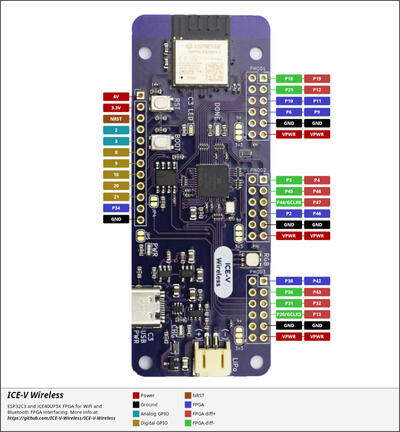
The ICE-V Wireless provides 1 row of reference, ESP32-C3, and iCE40 signals brought out to J3, as well as 3 PMOD connectors for interfacing directly to the iCE40 FPGA. Note that several of the iCE40 pins brought out to the PMOD connectors are capable of operating as differential pairs.
The J3 pins are 4V, 3.3V, NRST, GPIO2, GPIO3, GPIO8, GPIO9, GPIO10, GPIO20, GPIO21, FPGA_P34, and GND. Note that GPIO2 and GPIO3 may be configured for ADC operation.
For PMOD details, please refer to the PMOD Specification [9] and the image below.
System Requirements
Binary Blobs
Espressif HAL requires RF binary blobs in order work. Run the command below to retrieve those files.
west blobs fetch hal_espressif
Note
It is recommended running the command above after west update.
Programming and Debugging
The icev_wireless board supports the runners and associated west commands listed below.
| flash | debug | attach | rtt | debugserver | |
|---|---|---|---|---|---|
| esp32 | ✅ (default) | ||||
| openocd | ✅ | ✅ (default) | ✅ | ✅ | ✅ |
Simple Boot
The board could be loaded using the single binary image, without 2nd stage bootloader. It is the default option when building the application without additional configuration.
Note
Simple boot does not provide any security features nor OTA updates.
MCUboot Bootloader
User may choose to use MCUboot bootloader instead. In that case the bootloader must be built (and flashed) at least once.
There are two options to be used when building an application:
Sysbuild
Manual build
Note
User can select the MCUboot bootloader by adding the following line to the board default configuration file.
CONFIG_BOOTLOADER_MCUBOOT=y
Sysbuild
The sysbuild makes possible to build and flash all necessary images needed to bootstrap the board with the ESP32 SoC.
To build the sample application using sysbuild use the command:
west build -b <board> --sysbuild samples/hello_world
By default, the ESP32 sysbuild creates bootloader (MCUboot) and application images. But it can be configured to create other kind of images.
Build directory structure created by sysbuild is different from traditional Zephyr build. Output is structured by the domain subdirectories:
build/
├── hello_world
│   └── zephyr
│       ├── zephyr.elf
│       └── zephyr.bin
├── mcuboot
│    └── zephyr
│       ├── zephyr.elf
│       └── zephyr.bin
└── domains.yaml
Note
With --sysbuild option the bootloader will be re-build and re-flash
every time the pristine build is used.
For more information about the system build please read the Sysbuild (System build) documentation.
Manual Build
During the development cycle, it is intended to build & flash as quickly possible. For that reason, images can be built one at a time using traditional build.
The instructions following are relevant for both manual build and sysbuild. The only difference is the structure of the build directory.
Note
Remember that bootloader (MCUboot) needs to be flash at least once.
Build and flash applications as usual (see Building an Application and Run an Application for more details).
# From the root of the zephyr repository
west build -b <board> samples/hello_world
The usual flash target will work with the board configuration.
Here is an example for the Hello World
application.
# From the root of the zephyr repository
west build -b <board> samples/hello_world
west flash
Note
On targets that expose the built-in USB Serial/JTAG controller, the chip can
stay in download mode after west flash and will not boot the new image
until it is power cycled. If that happens, flash with a watchdog reset so the
chip restarts on its own:
west flash --reset-type watchdog-reset
Faster Flashing
To speed up the development cycle, --esp-skip-flashed skips writing the image
when the binary already in flash matches the one being flashed, verified with an
MD5 check on the device:
west flash --esp-skip-flashed
For an even faster reflash, --esp-diff writes only the regions that differ
from the previously flashed image. It compares against a locally cached copy
rather than reading the device, so use it only when the flash was not modified
by another tool, board, or manual write since the last west flash:
west flash --esp-diff
Progress output can be suppressed for cleaner logs, which is useful in CI:
west flash --esp-no-progress
Open the serial monitor using the following command:
west espressif monitor
After the board has automatically reset and booted, you should see the following message in the monitor:
***** Booting Zephyr OS vx.x.x-xxx-gxxxxxxxxxxxx *****
Hello World! <board>
Board variants using Snippets
ESP32 boards can be assembled with different modules using multiple combinations of SPI flash sizes, PSRAM sizes and PSRAM modes.
The snippets under snippets/espressif provide a modular way to apply these variations at build time without duplicating board definitions.
The following snippet-based variants are supported:
Snippet name |
Description |
|---|---|
Flash memory size |
|
|
Board with 4MB of flash |
|
Board with 8MB of flash |
|
Board with 16MB of flash |
|
Board with 32MB of flash |
|
Board with 64MB of flash |
|
Board with 128MB of flash |
PSRAM memory size |
|
|
Board with 2MB of PSRAM |
|
Board with 4MB of PSRAM |
|
Board with 8MB of PSRAM |
PSRAM utilization |
|
|
Relocate flash to PSRAM |
|
Wi-Fi buffers in PSRAM |
To apply a board variant, use the -S flag with west build:
west build -b <board> -S espressif-flash-32M -S espressif-psram-4M samples/hello_world
Note
These snippets are only applicable to boards with compatible hardware support for the selected flash/PSRAM configuration.
If no FLASH snippet is used, the board default flash size will be used.
If no PSRAM snippet is used, the board default psram size will be used.
Debugging
OpenOCD Debugging
Espressif chips require a custom OpenOCD build with ESP32-specific patches. Download the latest release from OpenOCD for ESP32 [3].
For detailed JTAG setup instructions, see JTAG debugging for ESP32 [5].
Zephyr Thread Awareness
OpenOCD supports Zephyr RTOS thread awareness, allowing GDB to:
List all threads with
info threadsDisplay thread names, priorities, and states
Switch between thread contexts
Show backtraces for any thread
Requirements:
OpenOCD ESP32 v0.12.0-esp32-20251215 [4] or later
Build with
CONFIG_DEBUG_THREAD_INFO=y
Example:
# From the root of the zephyr repository
west build -b <board> samples/hello_world -- -DCONFIG_DEBUG_THREAD_INFO=y -DOPENOCD=<path/to/bin/openocd> -DOPENOCD_DEFAULT_PATH=<path/to/openocd/share/openocd/scripts>
west debug
Using a Custom OpenOCD
The Zephyr SDK includes a bundled OpenOCD, but it may not have ESP32 support. To use the Espressif OpenOCD, specify the path when building:
# From the root of the zephyr repository
west build -b <board> samples/hello_world -- -DOPENOCD=/path/to/openocd -DOPENOCD_DEFAULT_PATH=/path/to/openocd/scripts
west debug