STM32 Debug Probe
Overview
The STM32 Debug Probe, is a inexpensive board for the STM32F103xb MCU.
Pin Mapping
The pinout diagram of STM32 Debug Probe can be seen:
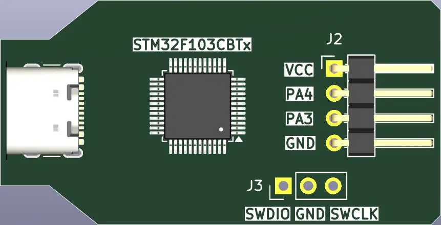
STLinkV2 connection:
The board can be flashed by using STLinkV2 with the following connections.
Pin |
STLINKv2 |
|---|---|
SWCLK |
Clock |
GND |
GND |
SWDIO |
SW IO |
Supported Features
The stm32_debug_probe board supports the hardware features listed below.
- on-chip / on-board
- Feature integrated in the SoC / present on the board.
- 2 / 2
-
Number of instances that are enabled / disabled.
Click on the label to see the first instance of this feature in the board/SoC DTS files. -
vnd,foo -
Compatible string for the Devicetree binding matching the feature.
Click on the link to view the binding documentation.
System Clock
The on-board 8Mhz crystal is used to produce a 72Mhz system clock with PLL.
Serial Port
The Zephyr console output is assigned to UART_2. Default settings are 115200 8N1.
On-Board LEDs
The board has one on-board LED that is connected to PB12.
Programming and Debugging
The stm32_debug_probe board supports the runners and associated west commands listed below.
| flash | debug |
|---|
Applications for the stm32_debug_probe board configuration can be
built and flashed in the usual way (see Building an Application and
Run an Application for more details).
Flashing
Here is an example for the Blinky application.
# From the root of the zephyr repository
west build -b stm32_debug_probe samples/basic/blinky
west flash
Debugging
You can debug an application in the usual way. Here is an example for the Hello World application.
# From the root of the zephyr repository
west build -b stm32_debug_probe samples/hello_world
west debug