Neonkey
96Boards Neonkey
Overview
96Boards Neonkey board is based on the STMicroelectronics STM32F411CE Cortex M4 CPU.
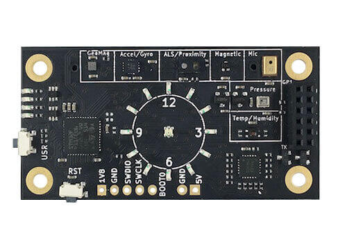
This board acts as a sensor hub platform for all 96Boards compliant family products. It can also be used as a standalone board.
Hardware
96Boards Neonkey provides the following hardware components:
STM32F411CE in UFQFPN48 package
ARM® 32-bit Cortex®-M4 CPU with FPU
84 MHz max CPU frequency
1.8V work voltage
512 KB Flash
128 KB SRAM
On board sensors:
Temperature/Humidity: SI7034-A10
Pressure: BMP280
ALS/Proximity: RPR-0521RS
Geomagnetic: BMM150
Accelerometer/Gyroscope: BMI160
AMR Hall sensor: MRMS501A
Microphone: SPK0415HM4H-B
4 User LEDs
15 General purpose LEDs
GPIO with external interrupt capability
I2C (3)
SPI (1)
I2S (1)
Supported Features
The 96b_neonkey board supports the hardware features listed below.
- on-chip / on-board
- Feature integrated in the SoC / present on the board.
- 2 / 2
-
Number of instances that are enabled / disabled.
Click on the label to see the first instance of this feature in the board/SoC DTS files. -
vnd,foo -
Compatible string for the Devicetree binding matching the feature.
Click on the link to view the binding documentation.
96b_neonkey/stm32f411xe target
On-target memory for this board target: 128 KiB of RAM, 512 KiB of Flash.
Type |
Location |
Description |
Compatible |
|---|---|---|---|
CPU |
on-chip |
ARM Cortex-M4F CPU1 |
|
ADC |
on-chip |
STM32F4 ADC1 |
|
Clock control |
on-chip |
STM32F4 RCC (Reset and Clock controller)1 |
|
on-chip |
STM32 HSE Clock1 |
||
on-chip |
|||
on-chip |
|||
on-chip |
STM32 Microcontroller Clock Output (MCO)2 |
||
Counter |
on-chip |
STM32 counters8 |
|
DMA |
on-chip |
STM32 DMA controller (V1)2 |
|
Flash controller |
on-chip |
STM32 Family flash controller1 |
|
GPIO & Headers |
on-chip |
STM32 GPIO Controller8 |
|
I2C |
on-chip |
STM32 I2C V1 controller3 |
|
I2S |
on-chip |
STM32 I2S controller5 |
|
Input |
on-board |
Group of GPIO-bound input keys1 |
|
Interrupt controller |
on-chip |
ARMv7-M NVIC (Nested Vectored Interrupt Controller)1 |
|
on-chip |
STM32 External Interrupt Controller1 |
||
LED |
on-board |
TI LP3943 LED1 |
|
on-board |
Group of GPIO-controlled LEDs1 |
||
Memory controller |
on-chip |
STM32 Battery Backed RAM1 |
|
MMC |
on-chip |
STM32 SDMMC Host Controller1 |
|
MTD |
on-chip |
STM32F4 flash memory1 |
|
NVMEM |
on-chip |
Fixed layout for Non-Volatile memory1 |
|
OTP memory |
on-chip |
||
PHY |
on-chip |
This binding is to be used by all the usb transceivers which are built-in with USB IP1 |
|
Pin control |
on-chip |
STM32 Pin controller1 |
|
Power management |
on-chip |
STM32 power controller1 |
|
PWM |
on-chip |
STM32 PWM8 |
|
Reset controller |
on-chip |
STM32 Reset and Clock Control (RCC) Controller1 |
|
RTC |
on-chip |
STM32 RTC1 |
|
Sensors |
on-chip |
STM32 quadrature decoder5 |
|
on-chip |
STM32 family TEMP node for production calibrated sensors with two calibration temperatures1 |
||
on-chip |
STM32 VREF+1 |
||
on-chip |
STM32 VBAT1 |
||
Serial controller |
on-chip |
||
SMbus |
on-chip |
STM32 SMBus controller3 |
|
SPI |
on-chip |
||
Timer |
on-chip |
ARMv7-M System Tick1 |
|
on-chip |
STM32 timers8 |
||
USB |
on-chip |
STM32 OTGFS controller1 |
|
Watchdog |
on-chip |
STM32 watchdog1 |
|
on-chip |
STM32 system window watchdog1 |
Connections and IOs
LED
LED1 / User1 LED = PB12
LED2 / User2 LED = PB13
LED3 / User3 LED = PB14
LED4 / User4 LED = PB15
System Clock
96Boards Neonkey can be driven by an internal oscillator as well as the main PLL clock. By default System clock is sourced by PLL clock at 84MHz, driven by internal oscillator.
Serial Port
On 96Boards Neonkey Zephyr console output is assigned to USART1. Default settings are 115200 8N1.
I2C
96Boards Neonkey board has up to 3 I2Cs. The default I2C mapping for Zephyr is:
I2C1_SCL : PB6
I2C1_SDA : PB7
I2C2_SCL : PB10
I2C2_SDA : PB3
I2C3_SCL : PA8
I2C3_SCL : PB4
SPI
96Boards Neonkey board has one SPI. The default SPI mapping for Zephyr is:
SPI1_NSS : PA4
SPI1_SCK : PA5
SPI1_MISO : PA6
SPI1_MOSI : PA7
Programming and Debugging
Building
Here is an example for building the Hello World application.
# From the root of the zephyr repository
west build -b 96b_neonkey samples/hello_world
Flashing
96Boards Neonkey can be flashed by two methods, one using the ROM bootloader and another using the SWD debug port (which requires additional hardware).
Using ROM bootloader:
ROM bootloader can be triggered by the following pattern:
Connect BOOT0 to VDD (link JTAG pins 1 and 5 on P4 header)
Press and hold the USR button
Press and release the RST button
More detailed information on activating the ROM bootloader can be found in Chapter 29 of Application note AN2606 [1]. The ROM bootloader supports flashing via UART, I2C and SPI protocols.
For flashing, stm32flash [2] command line utility can be used. The following
command will flash the zephyr.bin binary to the Neonkey board using UART
and starts its execution:
$ stm32flash -w zephyr.bin -v -g 0x08000000 /dev/ttyS0
Note
The above command assumes that Neonkey board is connected to
serial port /dev/ttyS0.
Using SWD debugger:
For flashing via SWD debug port, 0.1” male header must be soldered at P4 header available at the bottom of the board, near RST button.
Use the Black Magic Debug Probe [3] as an SWD programmer, which can be connected to the P4 header using its flying leads and its 20 Pin JTAG Adapter Board Kit. When plugged into your host PC, the Black Magic Debug Probe enumerates as a USB serial device as documented on its Getting started page [4].
It also uses the GDB binary provided with the Zephyr SDK,
arm-zephyr-eabi-gdb. Other GDB binaries, such as the GDB from GCC
ARM Embedded, can be used as well.
$ arm-zephyr-eabi-gdb -q zephyr.elf
(gdb) target extended-remote /dev/ttyACM0
Remote debugging using /dev/ttyACM0
(gdb) monitor swdp_scan
Target voltage: 1.8V
Available Targets:
No. Att Driver
 1      STM32F4xx
(gdb) attach 1
Attaching to Remote target
0x080005d0 in ?? ()
(gdb) load
Debugging
After flashing 96Boards Neonkey, it can be debugged using the same GDB instance. To reattach, just follow the same steps above, till “attach 1”. You can then debug as usual with GDB. In particular, type “run” at the GDB prompt to restart the program you’ve flashed.