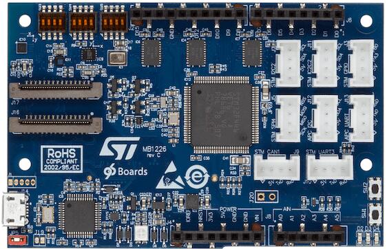
STM32 Sensor Mezzanine
96Boards STM32 Sensor Mezzanine
Overview
96Boards STM32 Sensor Mezzanine is based on the ST Microelectronics STM32F446VE Cortex M4 CPU.
This board acts as a mezzanine platform for all 96Boards CE compliant boards. It can also be used as a standalone board.
Hardware
96Boards STM32 Sensor Mezzanine provides the following hardware components:
STM32F446VE in LQFP100 package
ARM® 32-bit Cortex®-M4 CPU with FPU
180 MHz max CPU frequency
1.8V work voltage
512 KB Flash
128 KB SRAM
On board sensors:
Temperature/Pressure: STMicro LPS22HB
Accelerometer/Gyroscope: STMicro LSM6DS3H
Magnetometer: STMicro LIS3MDL
Microphone: STMicro MP34DT01
3User LEDs
GPIO with external interrupt capability
UART
I2C (2)
SPI (3)
I2S (1)
Supported Features
The 96b_stm32_sensor_mez board supports the hardware features listed below.
- on-chip / on-board
- Feature integrated in the SoC / present on the board.
- 2 / 2
-
Number of instances that are enabled / disabled.
Click on the label to see the first instance of this feature in the board/SoC DTS files. -
vnd,foo -
Compatible string for the Devicetree binding matching the feature.
Click on the link to view the binding documentation.
96b_stm32_sensor_mez/stm32f446xx target
On-target memory for this board target: 128 KiB of RAM, 512 KiB of Flash.
Type |
Location |
Description |
Compatible |
|---|---|---|---|
CPU |
on-chip |
ARM Cortex-M4F CPU1 |
|
ADC |
on-chip |
STM32F4 ADC3 |
|
Audio |
on-board |
STMicroelectronics MPXXDTYY digital PDM microphone family1 |
|
CAN |
on-chip |
STM32 CAN controller2 |
|
Clock control |
on-chip |
STM32F4 RCC (Reset and Clock controller)1 |
|
on-chip |
STM32 HSE Clock1 |
||
on-chip |
|||
on-chip |
|||
on-chip |
STM32 Clock multiplexer1 |
||
on-chip |
STM32 Microcontroller Clock Output (MCO)2 |
||
Counter |
on-chip |
STM32 counters8 |
|
DAC |
on-chip |
STM32 family DAC1 |
|
DMA |
on-chip |
||
Flash controller |
on-chip |
STM32 Family flash controller1 |
|
GPIO & Headers |
on-chip |
STM32 GPIO Controller8 |
|
I2C |
on-chip |
||
I2S |
on-chip |
||
on-chip |
STM32 SAI Block controller1 |
||
Input |
on-board |
Group of GPIO-bound input keys1 |
|
Interrupt controller |
on-chip |
ARMv7-M NVIC (Nested Vectored Interrupt Controller)1 |
|
on-chip |
STM32 External Interrupt Controller1 |
||
LED |
on-board |
Group of GPIO-controlled LEDs1 |
|
Memory controller |
on-chip |
STM32 Battery Backed RAM1 |
|
on-chip |
STM32 Flexible Memory Controller (FMC)1 |
||
on-chip |
STM32 Flexible Memory Controller (SDRAM controller)1 |
||
MMC |
on-chip |
STM32 SDMMC Host Controller1 |
|
MTD |
on-chip |
STM32F4 flash memory1 |
|
NVMEM |
on-chip |
Fixed layout for Non-Volatile memory1 |
|
OTP memory |
on-chip |
||
PHY |
on-chip |
This binding is to be used by all the usb transceivers which are built-in with USB IP2 |
|
Pin control |
on-chip |
STM32 Pin controller1 |
|
Power management |
on-chip |
STM32 power controller1 |
|
PWM |
on-chip |
||
Reset controller |
on-chip |
STM32 Reset and Clock Control (RCC) Controller1 |
|
RTC |
on-chip |
STM32 RTC1 |
|
Sensors |
on-board |
STMicroelectronics LIS3MDL magnetometer1 |
|
on-board |
STMicroelectronics LPS22HB pressure sensor1 |
||
on-chip |
STM32 quadrature decoder5 |
||
on-chip |
STM32 family TEMP node for production calibrated sensors with two calibration temperatures1 |
||
on-chip |
STM32 VREF+1 |
||
on-chip |
STM32 VBAT1 |
||
Serial controller |
on-chip |
||
on-chip |
|||
SMbus |
on-chip |
STM32 SMBus controller3 |
|
SPI |
on-chip |
||
Timer |
on-chip |
ARMv7-M System Tick1 |
|
on-chip |
|||
USB |
on-chip |
STM32 OTGFS controller1 |
|
on-chip |
STM32 OTGHS controller1 |
||
Watchdog |
on-chip |
STM32 watchdog1 |
|
on-chip |
STM32 system window watchdog1 |
Connections and IOs
LED
LED1 / User1 LED = PD10
LED2 / User2 LED = PD11
LED3 / User3 LED = PD12
System Clock
96Boards STM32 Sensor Mezzanine can be driven by an internal oscillator as well as the main PLL clock. In default board configuration, the 16MHz external oscillator is used to drive the main PLL clock to generate a System Clock (SYSCLK) at 84MHz. On the bus side, AHB/APB2 clocks runs at 84MHz, while APB1 clock runs at 42MHz.
Serial Port
On 96Boards STM32 Sensor Mezzanine, Zephyr console output is assigned to UART4 exposed via on-board Micro USB connector. Default settings are 115200 8N1.
The default USART mappings for the remaining ones are:
USART1: Connected to AP via UART0 on the 96Boards Low-Speed Header.
TX: PA9
RX: PA10
USART2: Connected to D0(RX) and D1(TX) on the Arduino Header.
TX: PD5
RX: PD6
USART3: Broken out to Grove connector J10.
TX: PD8
RX: PD9
I2C
96Boards STM32 Sensor Mezzanine board has up to 3 I2Cs. The default I2C mapping is:
I2C1_SCL : PB6
I2C1_SDA : PB7
I2C2_SCL : PB10
I2C2_SDA : PC12
I2C2 goes to the Groove connectors and can be used to attach external sensors.
SPI
96Boards STM32 Sensor Mezzanine board has 3 SPIs. SPI1 is used in slave mode as the communication bus with the AP. SPI2 is used in master mode to control the LSM6DS3H sensor. SPI4 is broken out to Grove Connector J5. The default SPI mapping is:
SPI1_NSS : PA4
SPI1_SCK : PA5
SPI1_MISO : PA6
SPI1_MOSI : PA7
SPI2_NSS : PB9
SPI2_SCK : PD3
SPI2_MISO : PB14
SPI2_MOSI : PB15
SPI4_NSS : PE11
SPI4_SCK : PE12
SPI4_MISO : PE13
SPI4_MOSI : PE14
PWM
96Boards STM32 Sensor Mezzanine board exposes 6 PWM channels on the Arduino connector. The default PWM mapping is:
PWM3_CH1 : PB4 : D9
PWM3_CH3 : PC8 : D3
PWM4_CH3 : PD14 : D6
PWM4_CH4 : PD15 : D5
PWM9_CH1 : PE5 : D12
PWM9_CH2 : PE6 : D11
I2S
96Boards STM32 Sensor Mezzanine board exposes 1 I2S port which is connected to the on-board ST MP34DT01 DMIC. The default I2S mapping is:
I2S2_SD : PC1
I2S2_CK : PC7
Programming and Debugging
Building
Here is an example for building the Hello World application.
# From the root of the zephyr repository
west build -b 96b_stm32_sensor_mez samples/hello_world
Flashing
96Boards STM32 Sensor Mezzanine board includes an ST-LINK/V2-1 embedded debug tool interface. This interface is supported by the openocd version included in the Zephyr SDK.
Flashing an application to 96Boards STM32 Sensor Mezzanine
Here is an example for the Hello World application.
Run a serial host program to connect with your 96Boards STM32 Sensor Mezzanine board.
$ minicom -b 115200 -D /dev/ttyACM0
Build and flash the application:
# From the root of the zephyr repository
west build -b 96b_stm32_sensor_mez samples/hello_world
west flash
You should see the following message on the console:
$ Hello World! 96b_stm32_sensor_mez
Debugging
You can debug an application in the usual way. Here is an example for the Hello World application.
# From the root of the zephyr repository
west build -b 96b_stm32_sensor_mez samples/hello_world
west debug