Avenger96
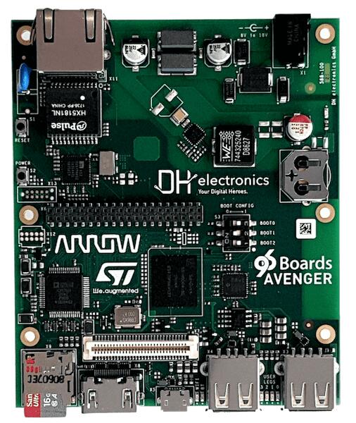
96Boards Avenger96
Overview
96Boards Avenger96 board is based on ST Microelectronics STM32MP157A multi-core processor, composed of a dual Cortex®-A7 and a single Cortex®-M4 core. Zephyr OS is ported to run on the Cortex®-M4 core.
Board features:
PMIC: STPMIC1A
RAM: 1024 Mbyte @ 533MHz
Storage:
eMMC: v4.51: 8 Gbyte
QSPI: 2Mbyte
EEPROM: 128 byte
microSD Socket: UHS-1 v3.01
Ethernet: 10/100/1000 Mbit/s, IEEE 802.3 Compliant
Wireless:
WiFi: 5 GHz & 2.4GHz IEEE 802.11a/b/g/n/ac
Bluetooth: v4.2 (BR/EDR/BLE)
USB:
Host - 2x type A, 2.0 high-speed
OTG: - 1x type micro-AB, 2.0 high-speed
HDMI: WXGA (1366x768)@ 60 fps, HDMI 1.4
Connectors:
40-Pin Low Speed Header
60-Pin High Speed Header
LEDs:
4x Green user LEDs
1x Blue Bluetooth LED
1x Yellow WiFi LED
1x Red power supply LED
More information about the board can be found at the 96Boards website.
Hardware
The STM32MP157A SoC provides the following hardware capabilities:
Core:
32-bit dual-core Arm® Cortex®-A7
L1 32-Kbyte I / 32-Kbyte D for each core
256-Kbyte unified level 2 cache
Arm® NEON™
32-bit Arm® Cortex®-M4 with FPU/MPU
Up to 209 MHz (Up to 703 CoreMark®)
Memories:
External DDR memory up to 1 Gbyte.
708 Kbytes of internal SRAM: 256 KB of AXI SYSRAM + 384 KB of AHB SRAM + 64 KB of AHB SRAM in backup domain.
Dual mode Quad-SPI memory interface
Flexible external memory controller with up to 16-bit data bus
Clock management:
Internal oscillators: 64 MHz HSI oscillator, 4 MHz CSI oscillator, 32 kHz LSI oscillator
External oscillators: 8-48 MHz HSE oscillator, 32.768 kHz LSE oscillator
6 × PLLs with fractional mode
General-purpose input/outputs:
Up to 176 I/O ports with interrupt capability
Interconnect matrix
3 DMA controllers
Communication peripherals:
6 × I2C FM+ (1 Mbit/s, SMBus/PMBus)
4 × UART + 4 × USART (12.5 Mbit/s, ISO7816 interface, LIN, IrDA, SPI slave)
6 × SPI (50 Mbit/s, including 3 with full duplex I2S audio class accuracy)
4 × SAI (stereo audio: I2S, PDM, SPDIF Tx)
SPDIF Rx with 4 inputs
HDMI-CEC interface
MDIO Slave interface
3 × SDMMC up to 8-bit (SD / e•MMC™ / SDIO)
2 × CAN controllers supporting CAN FD protocol, TTCAN capability
2 × USB 2.0 high-speed Host+ 1 × USB 2.0 full-speed OTG simultaneously
10/100M or Gigabit Ethernet GMAC (IEEE 1588v2 hardware, MII/RMII/GMII/RGMI)
8- to 14-bit camera interface up to 140 Mbyte/s
6 analog peripherals
2 × ADCs with 16-bit max. resolution.
1 × temperature sensor
2 × 12-bit D/A converters (1 MHz)
1 × digital filters for sigma delta modulator (DFSDM) with 8 channels/6 filters
Internal or external ADC/DAC reference VREF+
Graphics:
3D GPU: Vivante® - OpenGL® ES 2.0
LCD-TFT controller, up to 24-bit // RGB888, up to WXGA (1366 × 768) @60 fps
MIPI® DSI 2 data lanes up to 1 GHz each
Timers:
2 × 32-bit timers with up to 4 IC/OC/PWM or pulse counter and quadrature (incremental) encoder input
2 × 16-bit advanced motor control timers
10 × 16-bit general-purpose timers (including 2 basic timers without PWM)
5 × 16-bit low-power timers
RTC with sub-second accuracy and hardware calendar
2 × 4 Cortex®-A7 system timers (secure, non-secure, virtual, hypervisor)
1 × SysTick Cortex®-M4 timer
Hardware acceleration:
HASH (MD5, SHA-1, SHA224, SHA256), HMAC
2 × true random number generator (3 oscillators each)
2 × CRC calculation unit
Debug mode:
Arm® CoreSight™ trace and debug: SWD and JTAG interfaces
8-Kbyte embedded trace buffer
3072-bit fuses including 96-bit unique ID, up to 1184-bit available for user
More information about STM32P157A can be found here:
Supported Features
The 96b_avenger96 board supports the hardware features listed below.
- on-chip / on-board
- Feature integrated in the SoC / present on the board.
- 2 / 2
-
Number of instances that are enabled / disabled.
Click on the label to see the first instance of this feature in the board/SoC DTS files. -
vnd,foo -
Compatible string for the Devicetree binding matching the feature.
Click on the link to view the binding documentation.
96b_avenger96/stm32mp157cxx target
On-target memory for this board target: 320 KiB of RAM, 64 KiB of Flash.
Type |
Location |
Description |
Compatible |
|---|---|---|---|
CPU |
on-chip |
ARM Cortex-M4 CPU1 |
|
Clock control |
on-chip |
STM32MP1 RCC (Reset and Clock controller)1 |
|
on-chip |
STM32 HSE Clock1 |
||
Counter |
on-chip |
STM32 counters2 |
|
CRC |
on-chip |
STM32 CRC calculation unit2 |
|
Display |
on-chip |
STM32 LCD-TFT display controller1 |
|
DMA |
on-chip |
STM32 DMA controller (V1)2 |
|
on-chip |
STM32 DMAMUX controller1 |
||
GPIO & Headers |
on-chip |
STM32 GPIO Controller11 |
|
I2C |
on-chip |
STM32 I2C V2 controller1 |
|
Interrupt controller |
on-chip |
ARMv7-M NVIC (Nested Vectored Interrupt Controller)1 |
|
on-chip |
STM32G0 External Interrupt Controller1 |
||
IPM |
on-chip |
STM32 IPCC MAILBOX1 |
|
LED |
on-board |
Group of GPIO-controlled LEDs1 |
|
Pin control |
on-chip |
STM32 Pin controller1 |
|
PWM |
on-chip |
STM32 PWM2 |
|
Reset controller |
on-chip |
STM32 Reset and Clock Control (RCC) Controller1 |
|
Serial controller |
on-chip |
STM32 USART3 |
|
on-chip |
|||
SMbus |
on-chip |
STM32 SMBus controller1 |
|
SPI |
on-chip |
STM32H7 SPI controller5 |
|
Timer |
on-chip |
ARMv7-M System Tick1 |
|
on-chip |
STM32 timers2 |
||
Watchdog |
on-chip |
STM32 system window watchdog1 |
Connections and IOs
96Boards Avenger96 Board schematic is available here: Avenger96 board schematics.
Default Zephyr Peripheral Mapping:
UART_7 TX/RX/RTS/CTS : PE8/PE7/PE9/PE10 (UART console)
UART_4 TX/RX : PD1/PB2
System Clock
The Cortex®-M4 Core is configured to run at a 209 MHz clock speed. This value must match the configured mlhclk_ck frequency.
Serial Port
96Boards Avenger96 board has 3 U(S)ARTs. The Zephyr console output is assigned by default to the RAM console to be dumped by the Linux Remoteproc Framework on Cortex®-A7 core. Alternatively, Zephyr console output can be assigned to UART7 which is disabled by default. UART console can be enabled through board’s devicetree and 96b_avenger96_defconfig board file (or prj.conf project files), and will disable existing RAM console output. Default UART console settings are 115200 8N1.
Programming and Debugging
The STM32MP157A doesn’t have QSPI flash for the Cortex®-M4 and it needs to be started by the Cortex®-A7 core. The Cortex®-A7 core is responsible to load the Cortex®-M4 binary application into the RAM, and get the Cortex®-M4 out of reset. The Cortex®-A7 can perform these steps at bootloader level or after the Linux system has booted.
The Cortex®-M4 can use up to 2 different RAMs. The program pointer starts at address 0x00000000 (RETRAM), the vector table should be loaded at this address These are the memory mappings for Cortex®-A7 and Cortex®-M4:
Region |
Cortex®-A7 |
Cortex®-M4 |
Size |
|---|---|---|---|
RETRAM |
0x38000000-0x3800FFFF |
0x00000000-0x0000FFFF |
64KB |
MCUSRAM |
0x10000000-0x1005FFFF |
0x10000000-0x1005FFFF |
384KB |
DDR |
0xC0000000-0xFFFFFFFF |
up to 1 GB |
Refer to stm32mp157 boot Cortex-M4 firmware wiki page for instruction to load and start the Cortex-M4 firmware.
Debugging
You can debug an application using OpenOCD and GDB. The Solution proposed below is based on the Linux STM32MP1 SDK OpenOCD and is available only for a Linux environment. The firmware must first be loaded by the Cortex®-A7. Developer then attaches the debugger to the running Zephyr using OpenOCD.
Prerequisite
install stm32mp1 developer package.
start OpenOCD in a dedicated terminal
Start up the sdk environment:
source <SDK installation directory>/environment-setup-cortexa7hf-neon-vfpv4-openstlinux_weston-linux-gnueabi
Start OpenOCD:
${OECORE_NATIVE_SYSROOT}/usr/bin/openocd -s ${OECORE_NATIVE_SYSROOT}/usr/share/openocd/scripts -f board/stm32mp15x_ev1_jlink_jtag.cfg
run gdb in Zephyr environment
# On Linux
cd $ZEPHYR_BASE/samples/hello_world
mkdir -p build && cd build

# Use cmake to configure a Ninja-based build system:
cmake -GNinja -DBOARD=96b_avenger96 ..

# Now run ninja on the generated build system:
ninja debug