Aerocore2
96Boards Aerocore2
Overview
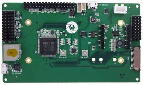
The 96Boards Aerocore2 Mezzanine is based on the STMicroelectronics STM32F427VIT6 Cortex-M4 CPU primarily designed for use in drones. This board acts as a mezzanine platform for all 96Boards CE compliant boards. It can also be used as a standalone board.
Hardware
96Boards Aerocore2 provides the following hardware components:
STM32F427VIT6 in LQFP100 package
ARM® 32-bit Cortex®-M4 CPU with FPU
168 MHz max CPU frequency
VDD from 1.7 V to 3.6 V
2048 KB Flash
256 KB SRAM
GPIO with external interrupt capability
12-bit ADC with 16 channels
RTC
Advanced-control Timers (2)
General Purpose Timers (10)
Watchdog Timers (2)
USART/UART (4)
I2C (3)
SPI (3)
SDIO
USB 2.0 OTG FS
DMA Controller
More information about STM32F427VIT6 can be found here:
Supported Features
The 96b_aerocore2 board supports the hardware features listed below.
- on-chip / on-board
- Feature integrated in the SoC / present on the board.
- 2 / 2
-
Number of instances that are enabled / disabled.
Click on the label to see the first instance of this feature in the board/SoC DTS files. -
vnd,foo -
Compatible string for the Devicetree binding matching the feature.
Click on the link to view the binding documentation.
96b_aerocore2/stm32f427xx target
On-target memory for this board target: 192 KiB of RAM, 2 MiB of Flash.
Type |
Location |
Description |
Compatible |
|---|---|---|---|
CPU |
on-chip |
ARM Cortex-M4F CPU1 |
|
ADC |
on-chip |
||
CAN |
on-chip |
STM32 CAN controller2 |
|
Clock control |
on-chip |
STM32F4 RCC (Reset and Clock controller)1 |
|
on-chip |
STM32 HSE Clock1 |
||
on-chip |
|||
on-chip |
|||
on-chip |
STM32 Microcontroller Clock Output (MCO)2 |
||
Counter |
on-chip |
STM32 counters14 |
|
DAC |
on-chip |
STM32 family DAC1 |
|
DMA |
on-chip |
STM32 DMA controller (V1)2 |
|
Ethernet |
on-chip |
ST STM32 Ethernet MAC, a child node of the Ethernet controller1 |
|
on-chip |
STM32 MDIO Controller1 |
||
Flash controller |
on-chip |
STM32 Family flash controller1 |
|
GPIO & Headers |
on-chip |
STM32 GPIO Controller11 |
|
I2C |
on-chip |
||
I2S |
on-chip |
STM32 I2S controller2 |
|
on-chip |
STM32 SAI Block controller1 |
||
Interrupt controller |
on-chip |
ARMv7-M NVIC (Nested Vectored Interrupt Controller)1 |
|
on-chip |
STM32 External Interrupt Controller1 |
||
LED |
on-board |
Group of GPIO-controlled LEDs1 |
|
Memory controller |
on-chip |
STM32 Battery Backed RAM1 |
|
on-chip |
STM32 Flexible Memory Controller (FMC)1 |
||
on-chip |
STM32 Flexible Memory Controller (SDRAM controller)1 |
||
MMC |
on-chip |
STM32 SDMMC Host Controller1 |
|
MTD |
on-chip |
STM32F4 flash memory1 |
|
NVMEM |
on-chip |
Fixed layout for Non-Volatile memory1 |
|
OTP memory |
on-chip |
||
PHY |
on-chip |
This binding is to be used by all the usb transceivers which are built-in with USB IP2 |
|
Pin control |
on-chip |
STM32 Pin controller1 |
|
Power management |
on-chip |
STM32 power controller1 |
|
PWM |
on-chip |
||
Reset controller |
on-chip |
STM32 Reset and Clock Control (RCC) Controller1 |
|
RNG |
on-chip |
STM32 Random Number Generator1 |
|
RTC |
on-chip |
STM32 RTC1 |
|
Sensors |
on-chip |
STM32 quadrature decoder6 |
|
on-chip |
STM32 family TEMP node for production calibrated sensors with two calibration temperatures1 |
||
on-chip |
STM32 VREF+1 |
||
on-chip |
STM32 VBAT1 |
||
Serial controller |
on-chip |
||
on-chip |
|||
SMbus |
on-chip |
STM32 SMBus controller3 |
|
SPI |
on-chip |
STM32 SPI controller4 |
|
Timer |
on-chip |
ARMv7-M System Tick1 |
|
on-chip |
|||
USB |
on-chip |
STM32 OTGFS controller1 |
|
on-chip |
STM32 OTGHS controller1 |
||
Watchdog |
on-chip |
STM32 watchdog1 |
|
on-chip |
STM32 system window watchdog1 |
Connections and IOs
LED
LED1 / User1 LED = PE10
LED2 / User2 LED = PE9
External Connectors
Octal PWM Header (J1)
PIN # |
Signal Name |
STM32F427 Functions Pin |
PIN # |
Signal Name |
Pin # |
Signal Name |
|---|---|---|---|---|---|---|
1 |
PWM4_CH1 |
PD12 |
2 |
5.0v |
3 |
GND |
4 |
PWM4_CH2 |
PD13 |
5 |
5.0v |
6 |
GND |
7 |
PWM4_CH3 |
PD14 |
8 |
5.0v |
9 |
GND |
10 |
PWM4_CH4 |
PD15 |
11 |
5.0v |
12 |
GND |
13 |
PWM5_CH1 |
PA0 |
14 |
5.0v |
15 |
GND |
16 |
PWM5_CH2 |
PA1 |
17 |
5.0v |
18 |
GND |
19 |
PWM5_CH3 |
PA2 |
20 |
5.0v |
21 |
GND |
22 |
PWM5_CH4 |
PA3 |
23 |
5.0v |
24 |
GND |
IO Header J11
PIN # |
Signal Name |
PIN # |
Signal Name |
|---|---|---|---|
1 |
PB9 |
2 |
PB8* |
3 |
PC9 |
4 |
PB0 |
5 |
PE5 |
6 |
NA |
7 |
PE6 |
8 |
NA |
9 |
PC6 |
10 |
NA |
11 |
PC7 |
12 |
NA |
13 |
PC8 |
14 |
NA |
15 |
PA8 |
16 |
GND |
17 |
PA9 |
18 |
3v3 |
19 |
PA10 |
20 |
GND |
PB8 is connected to a watchdog buzzer, It needs to be pulsed every 10 seconds to keep the buzzer silent.
IO Header J5
PIN # |
Signal Name |
STM32F427 Functions Pin |
PIN # |
Signal Name |
STM32F427 Functions Pin |
|---|---|---|---|---|---|
1 |
AGND |
AGND |
2 |
ADC1_13 |
PC3 |
3 |
ADC1_12 |
PC2 |
4 |
ADC1_11 |
PC1 |
5 |
I2C_SDA |
PB11 |
6 |
GND |
GND |
7 |
I2C_SCL |
PB10 |
8 |
VCC 3v3 |
VCC 3v3 |
9 |
NC |
NC |
10 |
NC |
NC |
11 |
NC |
NC |
12 |
NC |
NC |
13 |
UART_TX 7 |
PE8 |
14 |
GND |
GND |
15 |
UART_RX 7 |
PE7 |
16 |
GND |
GND |
17 |
UART_TX 2 |
PD5 |
18 |
GND |
GND |
19 |
UART_TX 2 |
PD6 |
20 |
GND |
GND |
21 |
NC |
NC |
10 |
NC |
NC |
23 |
NC |
NC |
10 |
NC |
NC |
25 |
SPI1_NIRQ |
PC5 |
26 |
GND |
GND |
27 |
SPI1_CLK |
PA5 |
28 |
SPI1_MISO |
PA6 |
29 |
SPI1_CS0 |
PA4 |
30 |
SPI1_MOSI |
PA7 |
31 |
CAN_TX |
PD1 |
32 |
CANH |
NC |
33 |
CAN_RX |
PD0 |
34 |
CANL |
NC |
GPS connector J15
PIN # |
Signal Name |
STM32F427 Functions Pin |
|---|---|---|
1 |
V_OUT 5v |
NC |
2 |
UART1_TX |
PB6 |
3 |
UART1_RX |
PB7 |
4 |
VCC 3v3 |
NC |
5 |
GND |
GND |
Spektrum connector J3
PIN # |
Signal Name |
STM32F427 Functions Pin |
|---|---|---|
1 |
VCC 3v3 |
NC |
2 |
GND |
GND |
3 |
UART8_RX |
PE0 |
External Clock Sources
STM32F4 has one external oscillator. The frequency of the clock is 32.768 kHz. The internal 16MHz clock is used as the main clock.
Serial Port
96Boards Aerocore2 board has up to 4 U(S)ARTs. The Zephyr console output is assigned to USART7. Default settings are 115200 8N1.
I2C
96Boards Aerocore2 board has 1 I2C port. The default I2C mapping for Zephyr is:
I2C1_SCL : PB10
I2C1_SDA : PB11
SPI
96Boards Aerocore2 board has 1 SPI port. The default SPI mapping for Zephyr is:
SPI1_CS0 : PA4
SPI1_SCK : PA5
SPI1_MISO : PA6
SPI1_MOSI : PA7
USB
96Boards Aerocore2 board has a USB OTG dual-role device (DRD) controller that supports both device and host functions through its mini “OTG” USB connector. Only USB device functions are supported in Zephyr at the moment.
Programming and Debugging
There are 2 main entry points for flashing STM32F4X SoCs, one using the ROM bootloader, and another by using the SWD debug port (which requires additional hardware). Flashing using the ROM bootloader requires a special activation pattern, which can be triggered by using the BOOT0 pin. The ROM bootloader supports flashing via USB (DFU), UART, I2C and SPI. You can read more about how to enable and use the ROM bootloader by checking the application note AN2606, page 109.
Flashing
Installing dfu-util
It is recommended to use at least v0.8 of dfu-util. The package available in debian/ubuntu can be quite old, so you might have to build dfu-util from source.
Flashing an Application to 96Boards Aerocore2
Connect the micro-USB cable to the USB OTG/STM_CONSOLE Aerocore2 port and to your computer. The board should power ON. Force the board into DFU mode by keeping the BOOT0 switch pressed while pressing and releasing the RST switch.
The BOOT button is located at the back-side of the PCB.
Confirm that the board is in DFU mode:
$ sudo dfu-util -l
dfu-util 0.8
Copyright 2005-2009 Weston Schmidt, Harald Welte and OpenMoko Inc.
Copyright 2010-2014 Tormod Volden and Stefan Schmidt
This program is Free Software and has ABSOLUTELY NO WARRANTY
Please report bugs to dfu-util@lists.gnumonks.org
Found DFU: [0483:df11] ver=2200, devnum=15, cfg=1, intf=0, alt=3, name="@Device Feature/0xFFFF0000/01*004 e", serial="3574364C3034"
Found DFU: [0483:df11] ver=2200, devnum=15, cfg=1, intf=0, alt=2, name="@OTP Memory /0x1FFF7800/01*512 e,01*016 e", serial="3574364C3034"
Found DFU: [0483:df11] ver=2200, devnum=15, cfg=1, intf=0, alt=1, name="@Option Bytes /0x1FFFC000/01*016 e", serial="3574364C3034"
Found DFU: [0483:df11] ver=2200, devnum=15, cfg=1, intf=0, alt=0, name="@Internal Flash /0x08000000/04*016Kg,01*064Kg,03*128Kg", serial="3574364C3034"
Found Runtime: [05ac:8290] ver=0104, devnum=2, cfg=1, intf=5, alt=0, name="UNKNOWN", serial="UNKNOWN"
You should see following confirmation on your Linux host:
$ dmesg
usb 1-2.1: new full-speed USB device number 14 using xhci_hcd
usb 1-2.1: New USB device found, idVendor=0483, idProduct=df11
usb 1-2.1: New USB device strings: Mfr=1, Product=2, SerialNumber=3
usb 1-2.1: Product: STM32 BOOTLOADER
usb 1-2.1: Manufacturer: STMicroelectronics
usb 1-2.1: SerialNumber: 3574364C3034
Then build and flash an application. Here is an example for the Hello World application.
# From the root of the zephyr repository
west build -b 96b_aerocore2 samples/hello_world
west flash
Connect a USB-TTL dongle to the UART_7 header port and to your computer. Run your favorite terminal program to listen for output.
$ minicom -D <tty_device> -b 115200
Replace <tty_device> with the port where the board 96Boards Aerocore2
can be found. For example, under Linux, /dev/ttyUSB0.
The -b option sets baud rate ignoring the value from config.
Press the Reset button and you should see the following message in your terminal:
Hello World! arm