RTL87x2G Model A Evaluation Board
Overview
RTL87x2G Model A evaluation board works along with an interchangeable daughterboard that houses an RTL87x2G series SoC.
The RTL87x2G Model A evaluation board is compatible with the following daughterboards:
RTL8762GRU/GRH Daughter Board
RTL8762GKU/GKH Daughter Board
RTL8762GC Daughter Board
Note
The RTL8762GC is currently not supported in Zephyr due to its reliance on external flash memory, which results in a variable flash size configuration.
Hardware
SoC Series
The RTL87x2G series comprises various chip types, each supporting different hardware features.
Below are the common hardware features of the RTL87x2G series:
Realtek KM4 core compatible with Arm Cortex-M55, running at 40MHz (Maximum 125MHz)
M-profile Vector Extension (MVE) for vector computation
32KB I-Cache, 16KB D-Cache, and 384KB SRAM
Select part numbers include MCM 4MB PSRAM
Hardware Keyscan / Quad Decode
Flash On-The-Fly Decryption
Embedded IR TX/RX
ISO7816 Interface
SPIC/SPI_m/SPI_s/SDIO/SD (eMMC)
Low Power Comparator
8-Channel AUXADC
24-bit HD ADC
CAN Bus
RMII for Ethernet
I2S/DAC/AMIC/DMIC/PDM
SPIC/RGB888/SEGCOM Display Interfaces
USB 2.0 High-Speed Interface
For detailed hardware information regarding specific part numbers of the RTL87x2G series, please refer to the RTL87x2G Introduction [1].
Board
The RTL87x2G Model A Evaluation Board supports the following features:
5V to 3.3V & 1.8V LDO power module
Supports QSPI (Group1) display interface
Supports audio module (AMIC, DMIC) interfaces
Red LED and RGB LED module
On-board FT232RL USB-to-UART converter
Supported Features
The rtl87x2g_evb_a board supports the hardware features listed below.
- on-chip / on-board
- Feature integrated in the SoC / present on the board.
- 2 / 2
-
Number of instances that are enabled / disabled.
Click on the label to see the first instance of this feature in the board/SoC DTS files. -
vnd,foo -
Compatible string for the Devicetree binding matching the feature.
Click on the link to view the binding documentation.
rtl87x2g_evb_a/rtl8762gkh target
On-target memory for this board target: 100 KiB of RAM, 1 MiB of Flash.
Type |
Location |
Description |
Compatible |
|---|---|---|---|
CPU |
on-chip |
ARM Cortex-M55 CPU1 |
|
Bluetooth |
on-chip |
Bluetooth HCI for Realtek Bee SoCs1 |
|
Clock control |
on-chip |
Bee clock controller1 |
|
on-chip |
Generic fixed-rate clock provider1 |
||
Counter |
on-chip |
Realtek Bee Timer implemented as Counter10 |
|
on-chip |
Realtek Bee Real-Time Clock (RTC) Counter1 |
||
DMA |
on-chip |
Bee DMA controller1 |
|
Flash controller |
on-chip |
Realtek Bee Nor Flash Controller1 |
|
GPIO & Headers |
on-chip |
||
I2C |
on-chip |
Bee I2C4 |
|
Input |
on-chip |
Bee Keyscan1 |
|
on-board |
Group of GPIO-bound input keys1 |
||
Interrupt controller |
on-chip |
ARMv8.1-M NVIC (Nested Vectored Interrupt Controller)1 |
|
LED |
on-board |
Group of GPIO-controlled LEDs1 |
|
MTD |
on-chip |
Realtek Bee Nor Flash1 |
|
Pin control |
on-chip |
Bee pin controller1 |
|
PWM |
on-chip |
Realtek Bee Timer implemented as PWM10 |
|
RNG |
on-chip |
Realtek Bee TRNG1 |
|
Sensors |
on-chip |
Bee AON_QDEC1 |
|
Serial controller |
on-chip |
||
SPI |
on-chip |
Bee SPI3 |
|
Timer |
on-chip |
ARMv8.1-M System Tick1 |
|
on-chip |
Realtek Bee Timer10 |
||
Watchdog |
on-chip |
Realtek Bee Core Watchdog Timer1 |
rtl87x2g_evb_a/rtl8762gku target
On-target memory for this board target: 100 KiB of RAM, 1 MiB of Flash.
Type |
Location |
Description |
Compatible |
|---|---|---|---|
CPU |
on-chip |
ARM Cortex-M55 CPU1 |
|
Bluetooth |
on-chip |
Bluetooth HCI for Realtek Bee SoCs1 |
|
Clock control |
on-chip |
Bee clock controller1 |
|
on-chip |
Generic fixed-rate clock provider1 |
||
Counter |
on-chip |
Realtek Bee Timer implemented as Counter10 |
|
on-chip |
Realtek Bee Real-Time Clock (RTC) Counter1 |
||
DMA |
on-chip |
Bee DMA controller1 |
|
Flash controller |
on-chip |
Realtek Bee Nor Flash Controller1 |
|
GPIO & Headers |
on-chip |
||
I2C |
on-chip |
Bee I2C4 |
|
Input |
on-chip |
Bee Keyscan1 |
|
on-board |
Group of GPIO-bound input keys1 |
||
Interrupt controller |
on-chip |
ARMv8.1-M NVIC (Nested Vectored Interrupt Controller)1 |
|
LED |
on-board |
Group of GPIO-controlled LEDs1 |
|
MTD |
on-chip |
Realtek Bee Nor Flash1 |
|
Pin control |
on-chip |
Bee pin controller1 |
|
PWM |
on-chip |
Realtek Bee Timer implemented as PWM10 |
|
RNG |
on-chip |
Realtek Bee TRNG1 |
|
Sensors |
on-chip |
Bee AON_QDEC1 |
|
Serial controller |
on-chip |
||
SPI |
on-chip |
Bee SPI3 |
|
Timer |
on-chip |
ARMv8.1-M System Tick1 |
|
on-chip |
Realtek Bee Timer10 |
||
Watchdog |
on-chip |
Realtek Bee Core Watchdog Timer1 |
rtl87x2g_evb_a/rtl8762grh target
On-target memory for this board target: 100 KiB of RAM, 512 KiB of Flash.
Type |
Location |
Description |
Compatible |
|---|---|---|---|
CPU |
on-chip |
ARM Cortex-M55 CPU1 |
|
Bluetooth |
on-chip |
Bluetooth HCI for Realtek Bee SoCs1 |
|
Clock control |
on-chip |
Bee clock controller1 |
|
on-chip |
Generic fixed-rate clock provider1 |
||
Counter |
on-chip |
Realtek Bee Timer implemented as Counter10 |
|
on-chip |
Realtek Bee Real-Time Clock (RTC) Counter1 |
||
DMA |
on-chip |
Bee DMA controller1 |
|
Flash controller |
on-chip |
Realtek Bee Nor Flash Controller1 |
|
GPIO & Headers |
on-chip |
||
I2C |
on-chip |
Bee I2C4 |
|
Input |
on-chip |
Bee Keyscan1 |
|
Interrupt controller |
on-chip |
ARMv8.1-M NVIC (Nested Vectored Interrupt Controller)1 |
|
LED |
on-board |
Group of GPIO-controlled LEDs1 |
|
MTD |
on-chip |
Realtek Bee Nor Flash1 |
|
Pin control |
on-chip |
Bee pin controller1 |
|
PWM |
on-chip |
Realtek Bee Timer implemented as PWM10 |
|
RNG |
on-chip |
Realtek Bee TRNG1 |
|
Sensors |
on-chip |
Bee AON_QDEC1 |
|
Serial controller |
on-chip |
||
SPI |
on-chip |
Bee SPI3 |
|
Timer |
on-chip |
ARMv8.1-M System Tick1 |
|
on-chip |
Realtek Bee Timer10 |
||
Watchdog |
on-chip |
Realtek Bee Core Watchdog Timer1 |
rtl87x2g_evb_a/rtl8762gru target
On-target memory for this board target: 100 KiB of RAM, 512 KiB of Flash.
Type |
Location |
Description |
Compatible |
|---|---|---|---|
CPU |
on-chip |
ARM Cortex-M55 CPU1 |
|
Bluetooth |
on-chip |
Bluetooth HCI for Realtek Bee SoCs1 |
|
Clock control |
on-chip |
Bee clock controller1 |
|
on-chip |
Generic fixed-rate clock provider1 |
||
Counter |
on-chip |
Realtek Bee Timer implemented as Counter10 |
|
on-chip |
Realtek Bee Real-Time Clock (RTC) Counter1 |
||
DMA |
on-chip |
Bee DMA controller1 |
|
Flash controller |
on-chip |
Realtek Bee Nor Flash Controller1 |
|
GPIO & Headers |
on-chip |
||
I2C |
on-chip |
Bee I2C4 |
|
Input |
on-chip |
Bee Keyscan1 |
|
Interrupt controller |
on-chip |
ARMv8.1-M NVIC (Nested Vectored Interrupt Controller)1 |
|
LED |
on-board |
Group of GPIO-controlled LEDs1 |
|
MTD |
on-chip |
Realtek Bee Nor Flash1 |
|
Pin control |
on-chip |
Bee pin controller1 |
|
PWM |
on-chip |
Realtek Bee Timer implemented as PWM10 |
|
RNG |
on-chip |
Realtek Bee TRNG1 |
|
Sensors |
on-chip |
Bee AON_QDEC1 |
|
Serial controller |
on-chip |
||
SPI |
on-chip |
Bee SPI3 |
|
Timer |
on-chip |
ARMv8.1-M System Tick1 |
|
on-chip |
Realtek Bee Timer10 |
||
Watchdog |
on-chip |
Realtek Bee Core Watchdog Timer1 |
Connections and IOs
Refer to the RTL87x2G Model A EVB Interfaces Distribution [2] for detailed information about the board interfaces.
System Clock
The RTL87x2G series SoC is configured to use the internal 32KHz clock as a source for the system clock.
Serial Port
The RTL87x2G series SoC has 6 UARTs. By default, UART2 is configured for the console and log output.
FLashing
Before flashing, please ensure the Realtek Bee Flash Programmer (MPCli) Host Tools is installed. This is the default flashing runner for the RTL87x2G series SoCs.
Flashing Realtek Images
To successfully run Zephyr on the RTL87x2G board, six essential images provided by Realtek must be programmed into the board, in addition to the Zephyr image.
To fetch these essential images, run the following command:
west blobs fetch hal_realtek --allow-regex 'bee/rtl87x2g/.*'
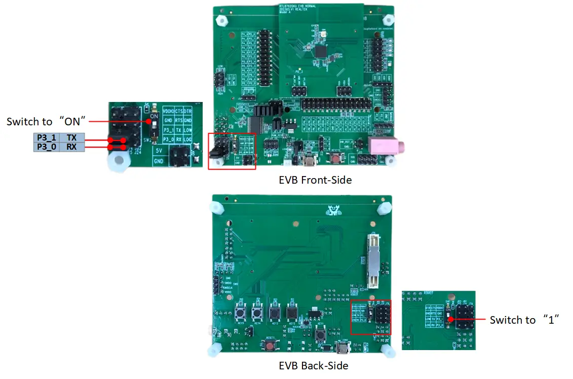
Enter Download Mode
The board is flashed through the serial interface provided by the on-board FT232RL USB-to-UART converter. Please follow these procedures to set up the hardware and enter download mode:
USB Connection: Connect a USB cable to the COM2 port located on the bottom left of the EVB.
Jumper Configuration: Use jumpers to connect P3_1 to TX and P3_0 to RX to utilize the on-board FT232RL USB-to-UART converter.
Toggle DIP Switch: Switch the DIP switch (located on either the front or back of the EVB) to the ‘ON’ position. This step grounds the P0_3 pin.
Reboot: Press the Reset button once to reboot the SoC and officially enter download mode.
After entering download mode, run the following command from the directory containing a build folder:
west flash --port <port_name> --mp-json <zephyr workspace>/modules/hal/realtek/bee/tools/mpcli/configs/rtl87x2g_essential_images.json
Note
The “west flash” command assumes you are running it from the root where the
builddirectory resides. If not, you must specify the build directory using the--build-diror-doption.Before flashing, ensure the serial port is available and not occupied by other applications (such as a serial console).
Flashing Zephyr
Follow the steps below to build and flash the Hello World application.
# From the root of the zephyr repository
west build -b rtl87x2g_evb_a/rtl8762gru samples/hello_world
west flash --port <port_name>
Enter Normal Mode
After successfully flashing the Zephyr image:
Toggle the DIP switch back to the ‘1’ (OFF) position.
Press the Reset button once to reboot the SoC. The device will then enter normal mode and execute the firmware.
Visualizing the message
The Zephyr console uses the same UART interface as the flashing process. Ensure the USB cable and jumpers remain connected as described above.
Open a Serial Terminal:
Open your preferred serial communication tool (e.g., PuTTY, Tera Term).
Connect to the appropriate COM port.
Configure the baud rate to 115200.
Reset the Board:
Press the reset button on the EVB.
You should see the output
Hello World! rtl87x2g_evb_a/rtl8762gruin your terminal.
Debugging
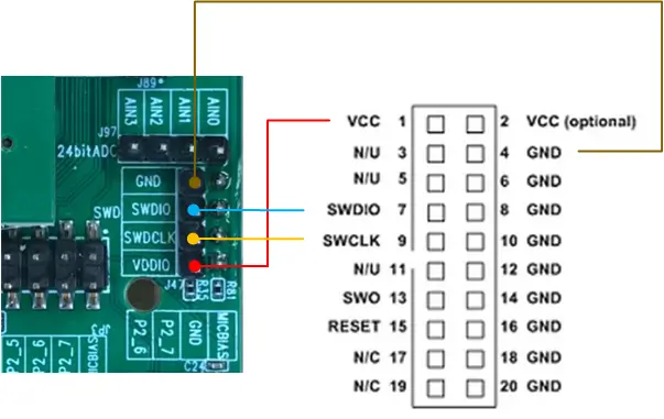
You can debug an application in the usual way using a J-Link debugger.
For J-link configuration details, please refer to the RTL87x2G J-Link Setup Guide [3]. The J-Link wiring diagram is shown below:
Here is an example for the Hello World application.
# From the root of the zephyr repository
west build -b rtl87x2g_evb_a/rtl8762gru samples/hello_world
west debug