GD32F470ZIT6 Core Board
Overview
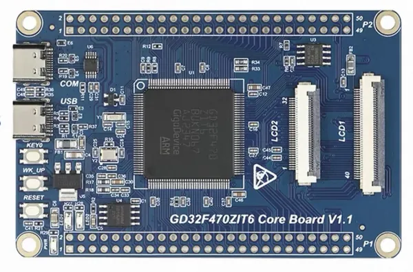
The GD32F470ZIT6 Core Board is a minimal system board based on the GigaDevice GD32F470ZIT6 Cortex-M4F MCU. It is produced by Waiken-Smart (慧勤智远) as the “GD32F470ZIT6 Core Board V1.1”.
The GD32F470ZIT6 features a single-core ARM Cortex-M4F MCU which can run up to 240 MHz with flash accesses at zero wait states, 2048 KiB of Flash and 768 KiB of SRAM.
Hardware
GD32F470ZIT6 MCU (LQFP144, 240 MHz)
2 x user LEDs (LED1 red on PA1, LED2 green on PA2, active-low)
2 x user push buttons (KEY0 on PC1, WK_UP on PA0, active-high)
1 x reset button
USB-C to UART (CH340X) on USART0 (TX PA9 / RX PA10)
AT24C02 EEPROM (256 B) on I2C0 (SCL PB6 / SDA PB7)
W25Q128 SPI NOR Flash (16 MB) on SPI4 (CS PF6, SCK PF7, MISO PF8, MOSI PF9)
32 MB SDRAM (W9825G6KH-6I)
TF card slot (SDIO)
RGB / 8080 / SPI LCD interfaces
SWD debug interface
Supported Features
The gd32f470zit6_core board supports the hardware features listed below.
- on-chip / on-board
- Feature integrated in the SoC / present on the board.
- 2 / 2
-
Number of instances that are enabled / disabled.
Click on the label to see the first instance of this feature in the board/SoC DTS files. -
vnd,foo -
Compatible string for the Devicetree binding matching the feature.
Click on the link to view the binding documentation.
gd32f470zit6_core/gd32f470 target
On-target memory for this board target: 704 KiB of RAM, 2 MiB of Flash.
Type |
Location |
Description |
Compatible |
|---|---|---|---|
CPU |
on-chip |
ARM Cortex-M4F CPU1 |
|
ADC |
on-chip |
GigaDevice GD32 ADC3 |
|
Clock control |
on-chip |
Gigadevice RCU - Clock Controller1 |
|
Counter |
on-chip |
GigaDevice GD32 timer14 |
|
DAC |
on-chip |
GigaDevice GD32 series DAC module1 |
|
DMA |
on-chip |
GD32 DMA controller with FIFO2 |
|
Flash controller |
on-chip |
There are three types GD32 FMC1 |
|
GPIO & Headers |
on-chip |
||
I2C |
on-chip |
||
Input |
on-board |
Group of GPIO-bound input keys1 |
|
Interrupt controller |
on-chip |
ARMv7-M NVIC (Nested Vectored Interrupt Controller)1 |
|
on-chip |
GigaDevice External Interrupt Controller1 |
||
LED |
on-board |
Group of GPIO-controlled LEDs1 |
|
Multi-Function Device |
on-chip |
Gigadevice RCU1 |
|
Miscellaneous |
on-chip |
GigaDevice GD32 System Configuration Registers1 |
|
MMU / MPU |
on-chip |
ARMv7-M Memory Protection Unit (MPU)1 |
|
MTD |
on-chip |
Flash memory binding of GD32 FMC v31 |
|
on-board |
I2C EEPROMs compatible with Atmel’s AT24 family1 |
||
on-board |
Properties supporting Zephyr spi-nor flash driver (over the Zephyr SPI API) control of serial flash memories using the standard M25P80-based command set1 |
||
Pin control |
on-chip |
GD32 Pin Controller (AF Model)1 |
|
PWM |
on-chip |
GigaDevice GD32 PWM12 |
|
Regulator |
on-chip |
GD32 Backup SRAM LDO (BLDO) regulator1 |
|
Reset controller |
on-chip |
Gigadevice RCU - Reset Controller1 |
|
Retained memory |
on-chip |
GD32 Backup SRAM retained memory1 |
|
RNG |
on-chip |
GigaDevice GD32 TRNG (True Random Number Generator)1 |
|
Serial controller |
on-chip |
||
SPI |
on-chip |
||
Timer |
on-chip |
ARMv7-M System Tick1 |
|
Watchdog |
on-chip |
GD32 free watchdog timer1 |
|
on-chip |
GD32 window watchdog timer1 |
Programming and Debugging
The gd32f470zit6_core board supports the runners and associated west commands listed below.
| flash | debug | attach | debugserver | rtt | reset | |
|---|---|---|---|---|---|---|
| jlink | ✅ (default) | ✅ (default) | ✅ | ✅ | ✅ | ✅ |
| openocd | ✅ | ✅ | ✅ | ✅ | ✅ |
The board can be programmed and debugged through its SWD interface (SWDIO on PA13, SWCLK on PA14). It does not include an onboard debug probe, so an external probe (e.g. SEGGER J-Link or CMSIS-DAP) is required.