CANBed RP2040
Overview
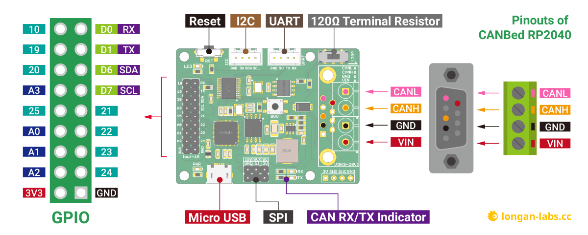
The Longan Labs CANBed RP2040 [1] board is based on the RP2040 microcontroller from Raspberry Pi Ltd. The board has a CAN bus controller and an I2C connector for easy sensor usage. It has a micro USB connector.
Hardware
Microcontroller Raspberry Pi RP2040, with a max frequency of 133 MHz
Dual ARM Cortex M0+ cores
264 kByte SRAM
2 Mbyte QSPI flash
13 GPIO pins
4 ADC pins
I2C
SPI
UART
Micro USB connector
Reset and boot buttons
Blue user LED
Grove I2C connector, compatible with Qwiic/Stemma QT if using adapter cable
Grove UART connector
CAN bus controller MCP2515
CAN bus transceiver SN65HVD230
Default Zephyr Peripheral Mapping
Label |
Pin |
Default pin mux |
|---|---|---|
LED |
GPIO18 |
Main header (sorted according to schematic pin numbering):
Label |
Pin |
Default pin mux |
Also in connector |
|---|---|---|---|
GND |
|||
24 |
GPIO24 |
||
23 |
GPIO23 |
||
22 |
GPIO22 |
||
21 |
GPIO21 |
||
SCL |
GPIO7 |
I2C1 SCL |
I2C connector |
SDA |
GPIO6 |
I2C1 SDA |
I2C connector |
TX |
GPIO0 |
UART0 TX |
UART connector |
RX |
GPIO1 |
UART0 RX |
UART connector |
10 |
GPIO10 |
||
19 |
GPIO19 |
||
20 |
GPIO20 |
||
A3 |
GPIO29 |
ADC3 |
|
25 |
GPIO25 |
||
A0 |
GPIO26 |
ADC0 |
|
A1 |
GPIO27 |
ADC1 |
|
A2 |
GPIO28 |
ADC2 |
|
3V3 |
Grove I2C connector (pins also available in the main header):
Label |
Pin |
Default pin mux |
|---|---|---|
SCL |
GPIO7 |
I2C1 SCL |
SDA |
GPIO6 |
I2C1 SDA |
3V3 |
||
GND |
Grove UART connector (pins also available in the main header):
Label |
Pin |
Default pin mux |
|---|---|---|
RX |
GPIO1 |
UART0 RX |
TX |
GPIO0 |
UART0 TX |
3V3 |
||
GND |
SPI header:
Label |
Pin |
Default pin mux |
|---|---|---|
MISO |
GPIO4 |
SPI0 MISO |
SCK |
GPIO2 |
SPI0 SCK |
8 |
GPIO8 |
|
GND |
||
MOSI |
GPIO3 |
SPI0 MOSI |
3V3 |
CAN controller:
Label |
Pin |
Default pin mux |
|---|---|---|
CANCS |
GPIO9 |
|
INT |
GPIO11 |
The CAN controller is also connected to the SPI0 pins SCK, MOSI and MISO (see above).
Supported Features
The canbed_rp2040 board supports the hardware features listed below.
- on-chip / on-board
- Feature integrated in the SoC / present on the board.
- 2 / 2
-
Number of instances that are enabled / disabled.
Click on the label to see the first instance of this feature in the board/SoC DTS files. -
vnd,foo -
Compatible string for the Devicetree binding matching the feature.
Click on the link to view the binding documentation.
canbed_rp2040/rp2040 target
On-target memory for this board target: 264 KiB of RAM, 2 MiB of Flash.
Type |
Location |
Description |
Compatible |
|---|---|---|---|
CPU |
on-chip |
ARM Cortex-M0+ CPU2 |
|
ADC |
on-chip |
Raspberry Pi Pico ADC1 |
|
CAN |
on-board |
MCP2515 SPI CAN controller1 |
|
Clock control |
on-chip |
Raspberry Pi Pico clock controller node1 |
|
on-chip |
|||
on-chip |
The representation of Raspberry Pi Pico’s PLL2 |
||
on-chip |
The representation of Raspberry Pi Pico ring oscillator1 |
||
on-chip |
The representation of Raspberry Pi Pico external oscillator1 |
||
Counter |
on-chip |
Raspberry Pi Pico timer1 |
|
DMA |
on-chip |
Raspberry Pi Pico DMA1 |
|
Flash controller |
on-chip |
Raspberry Pi Pico flash controller1 |
|
GPIO & Headers |
on-chip |
Raspberry Pi Pico GPIO1 |
|
on-chip |
Raspberry Pi Pico GPIO Port1 |
||
on-board |
STEMMA QT is a 4-pin JST-SH connector for I2C devices1 |
||
I2C |
on-chip |
||
Interrupt controller |
on-chip |
ARMv6-M NVIC (Nested Vectored Interrupt Controller) controller1 |
|
LED |
on-board |
Group of GPIO-controlled LEDs1 |
|
Mailbox |
on-chip |
Raspberry Pi Pico interprocessor mailbox1 |
|
Miscellaneous |
on-chip |
Raspberry Pi Pico PIO2 |
|
on-chip |
Raspberry Pi Pico SIO1 |
||
MTD |
on-chip |
Flash node1 |
|
Pin control |
on-chip |
Raspberry Pi Pico Pin Controller1 |
|
PWM |
on-chip |
Raspberry Pi Pico PWM1 |
|
Regulator |
on-chip |
Raspberry Pi Pico core supply regurator1 |
|
Reset controller |
on-chip |
Raspberry Pi Pico Reset Controller1 |
|
RTC |
on-chip |
Raspberry Pi Pico RTC1 |
|
Sensors |
on-chip |
Raspberry Pi Pico family temperature sensor node1 |
|
Serial controller |
on-chip |
||
SPI |
on-chip |
||
SRAM |
on-chip |
Generic on-chip SRAM1 |
|
Timer |
on-chip |
ARMv6-M System Tick1 |
|
USB |
on-chip |
Raspberry Pi Pico USB Device Controller1 |
|
Watchdog |
on-chip |
Raspberry Pi Pico Watchdog1 |
Programming and Debugging
The canbed_rp2040 board supports the runners and associated west commands listed below.
| flash | debug | rtt | attach | debugserver | reset | |
|---|---|---|---|---|---|---|
| blackmagicprobe | ✅ | ✅ | ✅ | |||
| jlink | ✅ | ✅ | ✅ | ✅ | ✅ | ✅ |
| openocd | ✅ | ✅ (default) | ✅ | ✅ | ✅ | |
| pyocd | ✅ | ✅ | ✅ | ✅ | ✅ | |
| uf2 | ✅ (default) |
By default programming is done via the USB connector. Press and hold the BOOT button, and then
press the RST button, and the device will appear as a USB mass storage unit.
Building your application will result in a build/zephyr/zephyr.uf2 file.
Drag and drop the file to the USB mass storage unit, and the board will be reprogrammed.
It is also possible to program and debug the board via the SWDIO and SWCLK pins.
Then a separate programming hardware tool is required, and for example the openocd
software is used. Typically the OPENOCD and OPENOCD_DEFAULT_PATH values should be set
when building, and the --runner openocd argument should be used when flashing.
For more details on programming RP2040-based boards, see Programming and Debugging.
Flashing
To run the Blinky sample:
# From the root of the zephyr repository
west build -b canbed_rp2040 samples/basic/blinky/
west flash
Try also the Hello World, Analog-to-Digital Converter (ADC) with devicetree and Controller Area Network (CAN) counter samples.
The use of the Grove/Qwiic/Stemma QT I2C connector is demonstrated using the Generic Light Sensor Polling sample and a separate shield:
# From the root of the zephyr repository
west build -b canbed_rp2040 --shield adafruit_veml7700 samples/sensor/light_polling
west flash