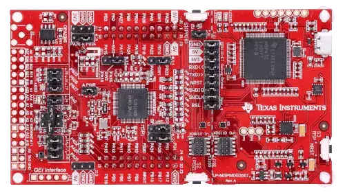
MSPM0G3507 Launchpad
Overview
MSPM0G350x microcontrollers (MCUs) are part of the MSP highly integrated, ultra-low-power 32-bit MCU family based on the enhanced Arm® Cortex®-M0+ 32-bit core platform operating at up to 80-MHz frequency. These cost-optimized MCUs offer high-performance analog peripheral integration, support extended temperature ranges from -40 °C to 125 °C, and operate with supply voltages ranging from 1.62 V to 3.6 V.
The MSPM0G350x devices provide up to 128KB embedded flash program memory with built-in error correction code (ECC) and up to 32KB SRAM with a hardware parity option. These MCUs also incorporate a memory protection unit, 7-channel DMA, math accelerator, and a variety of peripherals including
Analog.
Two 12-bit 4-Msps ADCs.
Configurable internal shared voltage reference.
One 12-bit 1-Msps DAC.
Three high speed comparators with built-in reference DACs.
Two zero-drift zero-crossover op-amps with programmable gain.
Digital.
Two 16-bit advanced control timers.
Five general-purpose timers.
One 16-bit general-purpose timer for QEI interface.
One 32-bit high resolution general-purpose timer.
Two 16-bit timers with deadband support and up to 12 PWM Channels.
Two windowed-watchdog timers.
One RTC with alarm and calendar modes.
Data Integrity and Encryption.
One AES HW accelerator capable of CTR, CBC, and ECB modes.
One Cyclic Redundancy Check (CRC) accelerator.
One True Random Number Generator (TRNG).
Communication.
Four UARTs, one with support for advanced modes such as LIN and Manchester.
Two I2C supporting SMBUS/PMBUS and speeds up to FM+ (1Mbits/s).
Two SPI, one with max speed 32Mbits/s.
One CAN interface supporting CAN 2.0 A or B and CAN-FD.
Zephyr uses the lp_mspm0g3507 board for building LP_MSPM0G3507
Features:
Onboard XDS110 debug probe
EnergyTrace technology available for ultra-low-power debugging
2 buttons, 1 LED and 1 RGB LED for user interaction
Temperature sensor circuit
Light sensor circuit
External OPA2365 (default buffer mode) for ADC (up to 4 Msps) evaluation
Onboard 32.768-kHz and 40-MHz crystals
RC filter for ADC input (unpopulated by default)
Details on the MSPM0G3507 LaunchPad can be found on the TI LP_MSPM0G3507 Product Page.
Supported Features
The lp_mspm0g3507 board supports the hardware features listed below.
- on-chip / on-board
- Feature integrated in the SoC / present on the board.
- 2 / 2
-
Number of instances that are enabled / disabled.
Click on the label to see the first instance of this feature in the board/SoC DTS files. -
vnd,foo -
Compatible string for the Devicetree binding matching the feature.
Click on the link to view the binding documentation.
lp_mspm0g3507/mspm0g3507 target
On-target memory for this board target: 32 KiB of RAM, 128 KiB of Flash.
Type |
Location |
Description |
Compatible |
|---|---|---|---|
CPU |
on-chip |
ARM Cortex-M0+ CPU1 |
|
ADC |
on-chip |
TI MSPM0 ADC122 |
|
CAN |
on-chip |
TI MSPM0 CANFD1 |
|
Clock control |
on-chip |
||
on-chip |
TI MSPM0 Phase Locked Loop1 |
||
on-chip |
|||
Comparator |
on-chip |
Texas Instruments MSPM0 Comparator Module with Reference DAC3 |
|
Counter |
on-chip |
TI MSPM0 counter node for MSPM0 SoCs4 |
|
Cryptographic accelerator |
on-chip |
Texas Instruments MSPM0 G series Advanced Encryption Standard (AES) Engine This peripheral provides AES-128 and AES-256 encryption and decryption1 |
|
DAC |
on-chip |
Texas Instruments MSPM0 G-Series Digital-to-Analog Converter (DAC)1 |
|
DMA |
on-chip |
TI MSPM0 DMA1 |
|
GPIO & Headers |
on-chip |
TI MSPM0 GPIO2 |
|
Interrupt controller |
on-chip |
ARMv6-M NVIC (Nested Vectored Interrupt Controller) controller1 |
|
LED |
on-board |
Group of GPIO-controlled LEDs1 |
|
on-board |
Group of PWM-controlled LEDs1 |
||
MTD |
on-board |
Fixed partitions of a flash (or other non-volatile storage) memory1 |
|
Pin control |
on-chip |
TI MSPM0 pinctrl node1 |
|
PWM |
on-chip |
||
Regulator |
on-chip |
Texas Instruments MSPM0 Voltage Reference (VREF) Regulator1 |
|
RNG |
on-chip |
Texas Instruments MSPM0 Series True Random Number Generator (TRNG)1 |
|
RTC |
on-chip |
Texas Instruments MSPM0 RTC Driver1 |
|
Serial controller |
on-chip |
||
SPI |
on-chip |
TEXAS INSTRUMENTS MSPM0 SERIAL PERIPHERAL INTERFACE (SPI)2 |
|
SRAM |
on-chip |
Generic on-chip SRAM1 |
|
Timer |
on-chip |
ARMv6-M System Tick1 |
|
on-chip |
TI MSPM0 Timer6 |
||
Watchdog |
on-chip |
MSPM0 Windowed Watchdog Timer2 |
Building and Flashing
Building
Follow the Getting Started Guide instructions for Zephyr application development.
For example, to build the blinky application for the MSPM0G3507 LaunchPad:
# From the root of the zephyr repository
west build -b lp_mspm0g3507 samples/hello_world
The resulting zephyr.bin binary in the build directory can be flashed onto
MSPM0G3507 LaunchPad using the steps mentioned below.
Flashing
Open OCD is used to program the flash memory on the devices. It may be necessary in earlier versions to use a branch of open OCD onto the device.
Before OpenOCD is public, one can clone This Repo, and then this can be built with
$ cd <cloned_OPENOCD_dir>
$ ./bootstrap (when building from the git repository)
$ ./configure
$ make
$ sudo make install
Then after the build, it is possible to flash the device by passing additional arguments to the flash command
$ west flash --openocd <path to cloned dir>/src/openocd --openocd-search <path to cloned dir>/tcl
Flashing using JLINK
$ west flash --runner jlink
Debugging
You can debug an application in the usual way. Here is an example for the Hello World application.
# From the root of the zephyr repository
west build -b lp_mspm0g3507 samples/hello_world
west debug
References
- TI MSPM0 MCU Page:
- TI MSPM0G3507 Product Page:
- TI MSPM0 SDK: