nRF51-VBLUno51
Overview
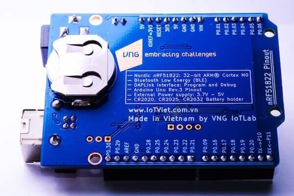
Zephyr uses the nrf51_vbluno51 board configuration to run on the VBLUno51 board, a VNG Bluetooth Low Energy UNO using an nRF51822 ARM processor.
More information about the board can be found at the VBLUno51 wiki page [1].
Hardware
VBLUno51 board has two external oscillators. The frequency of the slow clock is 32.768 kHz. The frequency of the main clock is 16 MHz.
- CPU:
Nordic nRF51822: ARM® Cortex® M0 32bit.
Bluetooth Low Energy interface.
256KB Flash, 32KB RAM.
UART(1), I2C(2), SPI(1), PWM(3), SWD, Timer 16bit(3).
21 digital channels, 6 ADC 10bit channels.
1 Led and 1 Button onboard.
GPIO Voltage: 0 - 3.3V.
- DAPLink (CMSIS-DAP) interface for program and debug:
USB MSD: Drag and Drop programming flash memory.
USB HID (DAP): CMSIS-DAP compliant debug channel.
USB CDC: Virtual COM port for log, trace and terminal emulation.
Supports hardware flow control features (RTS/CTS).
Energy monitoring for BLE module by current measurement (Only VBLUno51_EM)
FOTA (Firmware over the air): Upgrade firmware over BLE interface.
- Build good applications with:
Compiler and IDE: GCC, Keil MDK, IAR, Eclipse, Qt Creator.
Frameworks: Arduino, ARM mbed-OS, Zephyr-OS, Nordic SDK, RIOT-OS, MyNewt-OS, ChibiOS, NuttX RTOS
A lot of tutorials for Arduino, mbed-os and more.
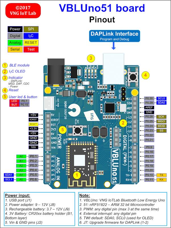
Pinout: Arduino Uno Rev3 compliant.
- Power:
USB port.
Power adapter: +9 -> +12V.
3V Battery: CR20xx holder
Rechargeable battery jump: +3.7 -> +12V
Open source: Hardware design, firmware, packages, tutorial and example codes
See VBLUno51 wiki page [1] for full documents and tutorials about the VBLUno51 board.
Supported Features
The nrf51_vbluno51 board supports the hardware features listed below.
- on-chip / on-board
- Feature integrated in the SoC / present on the board.
- 2 / 2
-
Number of instances that are enabled / disabled.
Click on the label to see the first instance of this feature in the board/SoC DTS files. -
vnd,foo -
Compatible string for the Devicetree binding matching the feature.
Click on the link to view the binding documentation.
nrf51_vbluno51/nrf51822 target
On-target memory for this board target: 32 KiB of RAM, 256 KiB of Flash.
Type |
Location |
Description |
Compatible |
|---|---|---|---|
CPU |
on-chip |
ARM Cortex-M0 CPU1 |
|
ADC |
on-chip |
nRF ADC node1 |
|
ARM architecture |
on-chip |
Nordic UICR (User Information Configuration Registers)1 |
|
on-chip |
Nordic nRF family MPU (Memory Protection Unit)1 |
||
on-chip |
Nordic nRF family SWI (Software Interrupt)6 |
||
Clock control |
on-chip |
Nordic nRF clock control node1 |
|
on-chip |
Nordic nRF high-frequency crystal oscillator (nRF51 series)1 |
||
Comparator |
on-chip |
Nordic nRF LPCOMP (analog Low-Power COMParator)1 |
|
Counter |
on-chip |
Nordic nRF timer node3 |
|
Cryptographic accelerator |
on-chip |
Nordic ECB (AES electronic codebook mode encryption)1 |
|
on-chip |
Nordic nRF family CCM (AES CCM mode encryption)1 |
||
Flash controller |
on-chip |
Nordic NVMC (Non-Volatile Memory Controller)1 |
|
GPIO & Headers |
on-chip |
NRF5 GPIOTE1 |
|
on-chip |
NRF5 GPIO1 |
||
I2C |
on-chip |
||
Input |
on-board |
Group of GPIO-bound input keys1 |
|
Interrupt controller |
on-chip |
ARMv6-M NVIC (Nested Vectored Interrupt Controller) controller1 |
|
LED |
on-board |
Group of GPIO-controlled LEDs1 |
|
Miscellaneous |
on-chip |
Nordic FICR (Factory Information Configuration Registers)1 |
|
on-chip |
Nordic nRF family PPI (Programmable Peripheral Interconnect)1 |
||
MTD |
on-chip |
Flash node1 |
|
Networking |
on-chip |
Nordic nRF family RADIO peripheral1 |
|
Pin control |
on-chip |
Nordic nRF family Pin Controller1 |
|
Power management |
on-chip |
Nordic nRF power control node1 |
|
PWM |
on-chip |
nRFx S/W PWM1 |
|
Retained memory |
on-chip |
Nordic GPREGRET (General Purpose Register Retention) device1 |
|
RNG |
on-chip |
Nordic nRF family RNG (Random Number Generator)1 |
|
RTC |
on-chip |
Nordic nRF RTC (Real-Time Counter)2 |
|
Sensors |
on-chip |
Nordic nRF family TEMP node1 |
|
on-chip |
Nordic nRF quadrature decoder (QDEC) node1 |
||
Serial controller |
on-chip |
Nordic nRF family UART1 |
|
SPI |
on-chip |
Nordic nRF family SPI (SPI master)2 |
|
SRAM |
on-chip |
Generic on-chip SRAM1 |
|
Watchdog |
on-chip |
Nordic nRF family WDT (Watchdog Timer)1 |
Connections and IOs
LED
LED = LED0 (green) = P0.7
More details

Programming and Debugging
The nrf51_vbluno51 board supports the runners and associated west commands listed below.
| flash | debug | rtt | attach | debugserver | |
|---|---|---|---|---|---|
| pyocd | ✅ (default) | ✅ (default) | ✅ | ✅ | ✅ |
Applications for the nrf51_vbluno51 board configuration can be
built and flashed in the usual way (see Building an Application
and Run an Application for more details).
Flashing
The VBLUno51 board has on-board DAPLink (CMSIS-DAP) interface for flashing and debugging. You do not need any other programming device. You only need to install pyOCD tool (https://pypi.python.org/pypi/pyOCD)
This tutorial uses the blinky application Blinky.
See the Getting Started Guide for general information on setting up your development environment. Then build and flash the application in the usual way.
# From the root of the zephyr repository
west build -b nrf51_vbluno51 samples/basic/blinky
west flash
Debugging
You can debug an application in the usual way. Here is an example for the Blinky application.
# From the root of the zephyr repository
west build -b nrf51_vbluno51 samples/basic/blinky
west debug