RuuviTag
Overview
RuuviTag is an advanced battery-operated open-source Bluetooth enabled sensor beacon platform capable of sending temperature, humidity, pressure, and motion information over Bluetooth Low Energy.
More information about the board can be found at the ruuvitag website [1].
Hardware
RuuviTag’s have the following physical features:
Nordic Semiconductor nRF52832 System-on-Chip
STMicroelectronics LIS2DH12 accelerometer
Bosch BME 280 temperature + relative air humidity + air pressure sensor
NFC™-A tag antenna
1000mAh CR2477 battery
2 buttons
1 Green LED
1 Red LED
IP67 Enclosure
Long range RF antenna
Supported Features
The ruuvi_ruuvitag board supports the hardware features listed below.
- on-chip / on-board
- Feature integrated in the SoC / present on the board.
- 2 / 2
-
Number of instances that are enabled / disabled.
Click on the label to see the first instance of this feature in the board/SoC DTS files. -
vnd,foo -
Compatible string for the Devicetree binding matching the feature.
Click on the link to view the binding documentation.
ruuvi_ruuvitag/nrf52832 target
On-target memory for this board target: 64 KiB of RAM, 512 KiB of Flash.
Type |
Location |
Description |
Compatible |
|---|---|---|---|
CPU |
on-chip |
ARM Cortex-M4F CPU1 |
|
ADC |
on-chip |
Nordic Semiconductor nRF family SAADC node1 |
|
ARM architecture |
on-chip |
Nordic UICR (User Information Configuration Registers)1 |
|
on-chip |
Nordic nRF family BPROT (Block Protection)1 |
||
on-chip |
Nordic EGU (Event Generator Unit)6 |
||
on-chip |
Nordic nRF family MWU (Memory Watch Unit)1 |
||
Audio |
on-chip |
Nordic PDM (Pulse Density Modulation interface)1 |
|
Clock control |
on-chip |
Nordic nRF clock control node1 |
|
on-chip |
Nordic nRF high-frequency crystal oscillator (nRF52 series)1 |
||
Comparator |
on-chip |
Nordic nRF COMP (analog COMParator)1 |
|
Counter |
on-chip |
Nordic nRF timer node5 |
|
Cryptographic accelerator |
on-chip |
Nordic ECB (AES electronic codebook mode encryption)1 |
|
on-chip |
Nordic nRF family CCM (AES CCM mode encryption)1 |
||
Debug |
on-chip |
ARMv7 instrumentation trace macrocell1 |
|
Flash controller |
on-chip |
Nordic NVMC (Non-Volatile Memory Controller)1 |
|
GPIO & Headers |
on-chip |
NRF5 GPIOTE1 |
|
on-chip |
NRF5 GPIO1 |
||
I2C |
on-chip |
Nordic nRF family TWIM (TWI master with EasyDMA)2 |
|
I2S |
on-chip |
Nordic I2S (Inter-IC sound interface)1 |
|
Input |
on-board |
Group of GPIO-bound input keys1 |
|
Interrupt controller |
on-chip |
ARMv7-M NVIC (Nested Vectored Interrupt Controller)1 |
|
LED |
on-board |
Group of GPIO-controlled LEDs1 |
|
Miscellaneous |
on-chip |
Nordic FICR (Factory Information Configuration Registers)1 |
|
on-chip |
Nordic nRF family PPI (Programmable Peripheral Interconnect)1 |
||
MTD |
on-chip |
Flash node1 |
|
Networking |
on-chip |
Nordic nRF family RADIO peripheral1 |
|
on-chip |
Nordic nRF family NFCT (Near Field Communication Tag)1 |
||
Pin control |
on-chip |
Nordic nRF family Pin Controller1 |
|
Power management |
on-chip |
Nordic nRF power control node1 |
|
PWM |
on-chip |
nRF PWM3 |
|
on-chip |
nRFx S/W PWM1 |
||
Regulator |
on-chip |
Nordic nRF5X regulator (fixed stage of the core supply)1 |
|
Retained memory |
on-chip |
Nordic GPREGRET (General Purpose Register Retention) device2 |
|
RNG |
on-chip |
Nordic nRF family RNG (Random Number Generator)1 |
|
RTC |
on-chip |
Nordic nRF RTC (Real-Time Counter)3 |
|
Sensors |
on-board |
BME280 integrated environmental sensor1 |
|
on-board |
STMicroelectronics LIS2DH 3-axis accelerometer accessed through I2C bus1 |
||
on-chip |
Nordic nRF family TEMP node1 |
||
on-chip |
Nordic nRF quadrature decoder (QDEC) node1 |
||
Serial controller |
on-chip |
Nordic nRF family UART1 |
|
SPI |
on-chip |
||
SRAM |
on-chip |
Generic on-chip SRAM1 |
|
Timer |
on-chip |
ARMv7-M System Tick1 |
|
Watchdog |
on-chip |
Nordic nRF family WDT (Watchdog Timer)1 |
Connections and IOs
LED
LED0 (red) = P0.17
LED1 (green) = P0.19
Pin descriptions
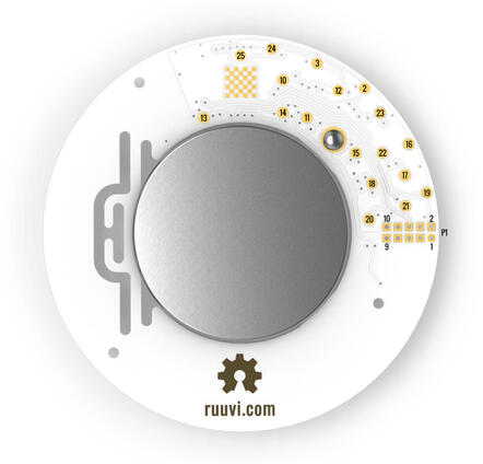
2 = P0.29 = SPI_SCK
3 = P0.28 = SPI_MISO
10 = P0.04 = GPIO (can be used as a GPIO / ADC pin)
11 = P0.05 = GPIO (can be used as a GPIO / ADC pin)
12 = P0.25 = SPI_MOSI
13 = P0.19 = LED2 (green) / GPIO (can be used as a GPIO pin but the LED will blink)
14 = P0.17 = LED1 (red) / GPIO (can be used as a GPIO pin but the LED will blink)
15 = P0.13 = Button / GPIO (can be used as a GPIO pin)
16 = GND (Battery’s negative contact)
17 = Battery’s positive contact
18 = Battery’s positive contact
19 = SWDIO
20 = SWDCLK
21 = P0.18 = SWO / GPIO (can be used as a GPIO pin)
22 = P0.21 = Reset / GPIO (can be used as a GPIO pin if no need to reset the device)
23 = GND (Battery’s negative contact)
24 = P0.31 = GPIO (can be used as a GPIO / ADC pin)
25 = P0.30 = GPIO (can be used as a GPIO / ADC pin)
GPIO = General Purpose Input Output pin
P1 = Standard 10-pin ARM Cortex debug connector (on RuuviTag Rev.B1-B5)
1 = VDD
2 = SWDIO
3 = GND (Battery’s negative contact)
4 = SWDCLK
5 = GND (Battery’s negative contact)
6 = SWO
7 = No Connect
8 = No Connect
9 = GND (Battery’s negative contact)
10 = Reset
P1 = TC2030 TagConnect (on RuuviTag Rev.B6)
1 = Battery’s positive contact
2 = SWDIO
3 = Reset
4 = SWDCLK
5 = GND (Battery’s negative contact)
6 = SWO
Programming and Debugging
The ruuvi_ruuvitag board supports the runners and associated west commands listed below.
| flash | debug | rtt | debugserver | attach | reset | |
|---|---|---|---|---|---|---|
| jlink | ✅ | ✅ (default) | ✅ | ✅ | ✅ | ✅ |
| nrfjprog | ✅ | |||||
| nrfutil | ✅ (default) |
Flashing
Build and flash applications as usual (see Building an Application and Run an Application for more details).
The easiest way to flash Zephyr onto a RuuviTag requires an external Ruuvi DEVKIT. More information about the board can be found at the ruuvitag devkit [2].
Once your tag is connected to the DEVKIT and connected to your PC, build and flash the application in the usual way.
# From the root of the zephyr repository
west build -b ruuvi_ruuvitag samples/basic/blinky
west flash
Advanced users may want to program the RuuviTag without the DEVKIT, this can be achieved via the SWDIO and SWDCLK pins located on the back of the RuuviTag.
Debugging
If using the Ruuvi DEVKIT refer to the Nordic nRF5x Segger J-Link page to learn about debugging Nordic boards with a Segger IC.