Legend
Overview
The Legend board family contains three revisions: 25hdd, 25ssd, and 35.
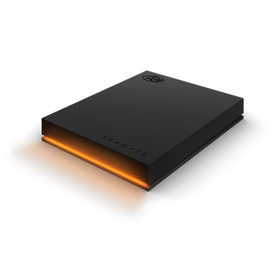
The Legend 2.5” HDD board (revision 25hdd) can be found in the Seagate FireCuda Gaming Hard Drive, Gaming Drive for Xbox and Gaming Drive for PlayStation devices. A 2.5” drive and two chips are embedded: an ASMedia ASM1153 USB-to-SATA bridge controller and a STM32F070 MCU. The former is handling the USB to HDD I/Os while the latter is dedicated to the LED effects. The two chips are connected together through I2C.
The Legend 2.5” SSD board (revision 25ssd) is found in the Seagate SSD Gaming Drive for Xbox. A Realtek RTS5411S USB hub is embedded and connected to a Phison U17 2.5” SSD, as well as a STM32F070 MCU.
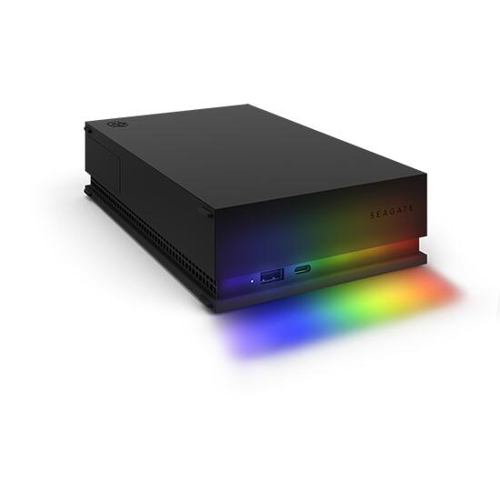
The Legend 3.5” board (revision 35) can be found in the Seagate FireCuda Gaming Hub and Gaming Drive Hub for Xbox devices. A Genesys Logic GL3523-S USB hub is connected to an ASMedia ASM1153 USB-to-SATA bridge controller and a STM32F070 MCU. The two chips are connected together using I2C.
On all boards, the Zephyr port is running on the STM32F070 MCU.
Hardware
STM32F070cb MCU:
ARM Cortex-M0+
16KB SRAM
128KB on-chip flash
External devices connected to the STM32F070cb MCU:
ASMedia ASM1153 USB-to-SATA bridge (I2C master on port 1) (HDD only)
6 (hdd) or 4 (ssd) Everlight B1414 LEDs connected on SPI1 MOSI
1 white LED (HDD only)
64KB external SPI flash connected on SPI2
Supported Features
The legend board supports the hardware features listed below.
- on-chip / on-board
- Feature integrated in the SoC / present on the board.
- 2 / 2
-
Number of instances that are enabled / disabled.
Click on the label to see the first instance of this feature in the board/SoC DTS files. -
vnd,foo -
Compatible string for the Devicetree binding matching the feature.
Click on the link to view the binding documentation.
legend@25hdd/stm32f070xb target
On-target memory for this board target: 16 KiB of RAM, 128 KiB of Flash.
Type |
Location |
Description |
Compatible |
|---|---|---|---|
CPU |
on-chip |
ARM Cortex-M0 CPU1 |
|
ADC |
on-chip |
STM32 ADC1 |
|
Clock control |
on-chip |
STM32F0/G0 RCC (Reset and Clock controller)1 |
|
on-chip |
STM32 HSE Clock1 |
||
on-chip |
|||
on-chip |
STM32 LSE Clock1 |
||
on-chip |
STM32F0/F3 Main PLL1 |
||
Counter |
on-chip |
STM32 counters8 |
|
DMA |
on-chip |
STM32 DMA controller (V2bis) for the stm32F0, stm32F1 and stm32L1 soc families1 |
|
Flash controller |
on-chip |
STM32 Family flash controller1 |
|
GPIO & Headers |
on-chip |
||
I2C |
on-chip |
||
Input |
on-chip |
STM32 Tocuh Sensing Controller (TSC) driver1 |
|
on-board |
Group of GPIO-bound input keys1 |
||
Interrupt controller |
on-chip |
ARMv6-M NVIC (Nested Vectored Interrupt Controller) controller1 |
|
on-chip |
STM32 External Interrupt Controller1 |
||
LED |
on-board |
Group of PWM-controlled LEDs1 |
|
LED strip |
on-board |
Worldsemi WS2812 LED strip, SPI binding1 |
|
MTD |
on-chip |
STM32 flash memory1 |
|
on-board |
Properties supporting Zephyr spi-nor flash driver (over the Zephyr SPI API) control of serial flash memories using the standard M25P80-based command set1 |
||
on-board |
Fixed partitions of a flash (or other non-volatile storage) memory1 |
||
NVMEM |
on-chip |
Fixed layout for Non-Volatile memory1 |
|
OTP memory |
on-chip |
STM32 embedded NVM OTP1 |
|
PHY |
on-chip |
This binding is to be used by all the usb transceivers which are built-in with USB IP1 |
|
Pin control |
on-chip |
STM32 Pin controller1 |
|
PWM |
on-chip |
||
Reset controller |
on-chip |
STM32 Reset and Clock Control (RCC) Controller1 |
|
RTC |
on-chip |
STM32 RTC1 |
|
Sensors |
on-chip |
STM32 VREF+1 |
|
on-chip |
STM32 TEMP for production calibrated sensors with a single calibration temperature1 |
||
Serial controller |
on-chip |
||
SMbus |
on-chip |
STM32 SMBus controller2 |
|
SPI |
on-chip |
STM32 SPI controller with embedded Rx and Tx FIFOs2 |
|
Timer |
on-chip |
ARMv6-M System Tick1 |
|
on-chip |
|||
USB |
on-chip |
STM32 USB controller1 |
|
Watchdog |
on-chip |
STM32 watchdog1 |
|
on-chip |
STM32 system window watchdog1 |
legend@25ssd/stm32f070xb target
On-target memory for this board target: 16 KiB of RAM, 128 KiB of Flash.
Type |
Location |
Description |
Compatible |
|---|---|---|---|
CPU |
on-chip |
ARM Cortex-M0 CPU1 |
|
ADC |
on-chip |
STM32 ADC1 |
|
Clock control |
on-chip |
STM32F0/G0 RCC (Reset and Clock controller)1 |
|
on-chip |
STM32 HSE Clock1 |
||
on-chip |
Generic fixed-rate clock provider3 |
||
on-chip |
STM32 LSE Clock1 |
||
on-chip |
STM32F0/F3 Main PLL1 |
||
Counter |
on-chip |
STM32 counters8 |
|
DMA |
on-chip |
STM32 DMA controller (V2bis) for the stm32F0, stm32F1 and stm32L1 soc families1 |
|
Flash controller |
on-chip |
STM32 Family flash controller1 |
|
GPIO & Headers |
on-chip |
||
I2C |
on-chip |
||
Input |
on-chip |
STM32 Tocuh Sensing Controller (TSC) driver1 |
|
on-board |
Group of GPIO-bound input keys1 |
||
Interrupt controller |
on-chip |
ARMv6-M NVIC (Nested Vectored Interrupt Controller) controller1 |
|
on-chip |
STM32 External Interrupt Controller1 |
||
LED strip |
on-board |
Worldsemi WS2812 LED strip, SPI binding1 |
|
MTD |
on-chip |
STM32 flash memory1 |
|
on-board |
Properties supporting Zephyr spi-nor flash driver (over the Zephyr SPI API) control of serial flash memories using the standard M25P80-based command set1 |
||
on-board |
Fixed partitions of a flash (or other non-volatile storage) memory1 |
||
NVMEM |
on-chip |
Fixed layout for Non-Volatile memory1 |
|
OTP memory |
on-chip |
STM32 embedded NVM OTP1 |
|
PHY |
on-chip |
This binding is to be used by all the usb transceivers which are built-in with USB IP1 |
|
Pin control |
on-chip |
STM32 Pin controller1 |
|
PWM |
on-chip |
STM32 PWM6 |
|
Reset controller |
on-chip |
STM32 Reset and Clock Control (RCC) Controller1 |
|
RTC |
on-chip |
STM32 RTC1 |
|
Sensors |
on-chip |
STM32 VREF+1 |
|
on-chip |
STM32 TEMP for production calibrated sensors with a single calibration temperature1 |
||
Serial controller |
on-chip |
||
SMbus |
on-chip |
STM32 SMBus controller2 |
|
SPI |
on-chip |
STM32 SPI controller with embedded Rx and Tx FIFOs2 |
|
Timer |
on-chip |
ARMv6-M System Tick1 |
|
on-chip |
STM32 timers8 |
||
USB |
on-chip |
STM32 USB controller1 |
|
Watchdog |
on-chip |
STM32 watchdog1 |
|
on-chip |
STM32 system window watchdog1 |
legend@35/stm32f070xb target
On-target memory for this board target: 16 KiB of RAM, 128 KiB of Flash.
Type |
Location |
Description |
Compatible |
|---|---|---|---|
CPU |
on-chip |
ARM Cortex-M0 CPU1 |
|
ADC |
on-chip |
STM32 ADC1 |
|
Clock control |
on-chip |
STM32F0/G0 RCC (Reset and Clock controller)1 |
|
on-chip |
STM32 HSE Clock1 |
||
on-chip |
Generic fixed-rate clock provider3 |
||
on-chip |
STM32 LSE Clock1 |
||
on-chip |
STM32F0/F3 Main PLL1 |
||
Counter |
on-chip |
STM32 counters8 |
|
DMA |
on-chip |
STM32 DMA controller (V2bis) for the stm32F0, stm32F1 and stm32L1 soc families1 |
|
Flash controller |
on-chip |
STM32 Family flash controller1 |
|
GPIO & Headers |
on-chip |
||
I2C |
on-chip |
||
Input |
on-chip |
STM32 Tocuh Sensing Controller (TSC) driver1 |
|
on-board |
Group of GPIO-bound input keys1 |
||
Interrupt controller |
on-chip |
ARMv6-M NVIC (Nested Vectored Interrupt Controller) controller1 |
|
on-chip |
STM32 External Interrupt Controller1 |
||
LED |
on-board |
Group of PWM-controlled LEDs1 |
|
LED strip |
on-board |
Worldsemi WS2812 LED strip, SPI binding1 |
|
MTD |
on-chip |
STM32 flash memory1 |
|
on-board |
Properties supporting Zephyr spi-nor flash driver (over the Zephyr SPI API) control of serial flash memories using the standard M25P80-based command set1 |
||
on-board |
Fixed partitions of a flash (or other non-volatile storage) memory1 |
||
NVMEM |
on-chip |
Fixed layout for Non-Volatile memory1 |
|
OTP memory |
on-chip |
STM32 embedded NVM OTP1 |
|
PHY |
on-chip |
This binding is to be used by all the usb transceivers which are built-in with USB IP1 |
|
Pin control |
on-chip |
STM32 Pin controller1 |
|
PWM |
on-chip |
||
Reset controller |
on-chip |
STM32 Reset and Clock Control (RCC) Controller1 |
|
RTC |
on-chip |
STM32 RTC1 |
|
Sensors |
on-chip |
STM32 VREF+1 |
|
on-chip |
STM32 TEMP for production calibrated sensors with a single calibration temperature1 |
||
Serial controller |
on-chip |
||
SMbus |
on-chip |
STM32 SMBus controller2 |
|
SPI |
on-chip |
STM32 SPI controller with embedded Rx and Tx FIFOs2 |
|
Timer |
on-chip |
ARMv6-M System Tick1 |
|
on-chip |
|||
USB |
on-chip |
STM32 USB controller1 |
|
Watchdog |
on-chip |
STM32 watchdog1 |
|
on-chip |
STM32 system window watchdog1 |
Connections and IOs
Name |
Function |
Usage |
|---|---|---|
PB6 |
I2C1 |
I2C1 SCL (HDD only) |
PB7 |
I2C1 |
I2C1 SDA (HDD only) |
PA10 |
UART |
USART0 RX |
PA9 |
UART |
USART0 TX |
PB0 |
PWM |
Activity LED (HDD only) |
PB12 |
SPI2 |
SPI2 Enable |
PB13 |
SPI2 |
SPI2 Clock |
PB14 |
SPI2 |
SPI2 MISO |
PB15 |
SPI2 |
SPI2 MOSI |
PA7 |
LED strip |
SPI1 MOSI |
PA12 |
USB |
USB DM (25ssd and 35 only) |
PA13 |
USB |
USB DP (25ssd and 35 only) |
Programming and Debugging
The legend board supports the runners and associated west commands listed below.
| flash | debug | rtt | attach | debugserver | reset | |
|---|---|---|---|---|---|---|
| jlink | ✅ | ✅ | ✅ | ✅ | ✅ | ✅ |
| openocd | ✅ (default) | ✅ (default) | ✅ | ✅ | ✅ |
Flashing
The STM32F070cb MCU can be flashed by connecting an external debug probe to the SWD port (on-board 4-pin header). In the default OpenOCD configuration, the ST Link interface is selected. You may need to replace it with the interface of your debug probe.
Once the debug probe is connected to both the Legend board and your host
computer, then you can simply run the west flash command to write a firmware
image into flash.
Debugging
Please refer to the Flashing section and run the west debug command
instead of west flash.