Hexiwear
Hexiwear
Overview
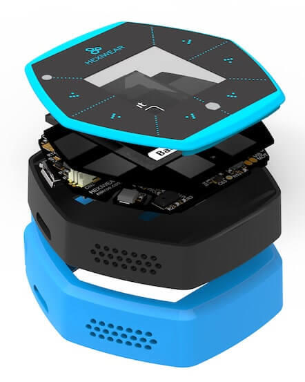
Hexiwear is powered by a Kinetis K64 microcontroller based on the ARM Cortex-M4 core. Another Kinetis wireless MCU, the KW40Z, provides Bluetooth Low Energy connectivity. Hexiwear also integrates a wide variety of sensors, as well as a user interface consisting of a 1.1” 96px x 96px full color OLED display and six capacitive buttons with haptic feedback.
Eye-catching Smart Watch form factor with powerful, low power Kinetis K6x MCU and 6 on-board sensors.
Designed for wearable applications with the onboard rechargeable battery, OLED screen and onboard sensors such as optical heart rate, accelerometer, magnetometer and gyroscope.
Designed for IoT end node applications with the onboard sensor’s such as temperature, pressure, humidity and ambient light.
Flexibility to let you add the sensors of your choice nearly 200 additional sensors through click boards.
Hardware
Main MCU: NXP Kinetis K64x (ARM Cortex-M4, 120 MHz, 1M Flash, 256K SRAM)
Wireless MCU: NXP Kinetis KW4x (ARM Cortex-M0+, Bluetooth Low Energy & 802.15.4 radio)
6-axis combo Accelerometer and Magnetometer NXP FXOS8700
3-Axis Gyroscope: NXP FXAS21002
Absolute Pressure sensor NXP MPL3115
Li-Ion/Li-Po Battery Charger NXP MC34671
Optical heart rate sensor Maxim MAX30101
Ambient Light sensor, Humidity and Temperature sensor
1.1” full color OLED display
Haptic feedback engine
190 mAh 2C Li-Po battery
Capacitive touch interface
RGB LED
For more information about the K64F SoC and Hexiwear board:
Supported Features
The hexiwear board supports the hardware features listed below.
- on-chip / on-board
- Feature integrated in the SoC / present on the board.
- 2 / 2
-
Number of instances that are enabled / disabled.
Click on the label to see the first instance of this feature in the board/SoC DTS files. -
vnd,foo -
Compatible string for the Devicetree binding matching the feature.
Click on the link to view the binding documentation.
hexiwear/mk64f12 target
On-target memory for this board target: 192 KiB of RAM, 1 MiB of Flash.
Type |
Location |
Description |
Compatible |
|---|---|---|---|
CPU |
on-chip |
ARM Cortex-M4F CPU1 |
|
ADC |
on-chip |
Kinetis ADC162 |
|
CAN |
on-chip |
NXP FlexCAN controller1 |
|
Clock control |
on-chip |
NXP Kinetis Multipurpose Clock generator (MCG) IP node1 |
|
on-chip |
Kinetis System Integration Module (SIM) IP node1 |
||
on-chip |
Generic fixed factor clock provider4 |
||
Counter |
on-chip |
NXP Periodic Interrupt Timer (PIT)1 |
|
on-chip |
Child node for the Periodic Interrupt Timer node, intended for an individual timer channel4 |
||
DAC |
on-chip |
NXP Kinetis MCUX DAC2 |
|
DMA |
on-chip |
NXP MCUX EDMA controller1 |
|
Ethernet |
on-chip |
NXP ENET IP Module1 |
|
on-chip |
NXP ENET MAC/L2 Device1 |
||
on-chip |
NXP ENET MDIO Features1 |
||
on-chip |
NXP ENET PTP (Precision Time Protocol) Clock1 |
||
Flash controller |
on-chip |
NXP Kinetis Flash Memory Module E (FTFE)1 |
|
GPIO & Headers |
on-chip |
Kinetis GPIO5 |
|
Hardware information |
on-chip |
NXP RCM get reset cause flags1 |
|
I2C |
on-chip |
||
Interrupt controller |
on-chip |
ARMv7-M NVIC (Nested Vectored Interrupt Controller)1 |
|
LED |
on-board |
Group of GPIO-controlled LEDs1 |
|
on-board |
Group of PWM-controlled LEDs1 |
||
MTD |
on-chip |
Flash node1 |
|
on-board |
Fixed partitions of a flash (or other non-volatile storage) memory1 |
||
Pin control |
on-chip |
NXP PORT Pin Controller5 |
|
on-chip |
NXP PORT Pin Controller1 |
||
PWM |
on-chip |
NXP FlexTimer Module (FTM) PWM controller1 |
|
Regulator |
on-board |
Fixed voltage regulators3 |
|
RNG |
on-chip |
Kinetis RNGA (Random Number Generator Accelerator)1 |
|
RTC |
on-chip |
NXP Real Time Clock (RTC)1 |
|
Sensors |
on-board |
MAX30101 heart rate and pulse oximeter sensor1 |
|
on-board |
FXOS8700 6-axis accelerometer/magnetometer sensor1 |
||
on-board |
FXAS21002 3-axis gyroscope sensor1 |
||
on-chip |
NXP Kinetis temperature sensor2 |
||
Serial controller |
on-chip |
||
SPI |
on-chip |
NXP DSPI controller3 |
|
SRAM |
on-chip |
Generic on-chip SRAM1 |
|
Timer |
on-chip |
ARMv7-M System Tick1 |
|
on-chip |
NXP FlexTimer Module (FTM)3 |
||
USB |
on-chip |
NPX Kinetis USBFSOTG Controller in device mode1 |
|
Watchdog |
on-chip |
Kinetis watchdog1 |
hexiwear/mkw40z4 target
On-target memory for this board target: 16 KiB of RAM, 512 KiB of Flash.
Type |
Location |
Description |
Compatible |
|---|---|---|---|
CPU |
on-chip |
ARM Cortex-M0+ CPU1 |
|
ADC |
on-chip |
Kinetis ADC161 |
|
Clock control |
on-chip |
NXP Kinetis Multipurpose Clock generator (MCG) IP node1 |
|
on-chip |
Kinetis System Integration Module (SIM) IP node1 |
||
on-chip |
Generic fixed factor clock provider2 |
||
Flash controller |
on-chip |
NXP Kinetis Flash Memory Module A (FTFA)1 |
|
GPIO & Headers |
on-chip |
||
Hardware information |
on-chip |
NXP RCM get reset cause flags1 |
|
I2C |
on-chip |
Kinetis I2C2 |
|
Interrupt controller |
on-chip |
ARMv6-M NVIC (Nested Vectored Interrupt Controller) controller1 |
|
MTD |
on-chip |
Flash node1 |
|
Pin control |
on-chip |
NXP PORT Pin Controller3 |
|
on-chip |
NXP PORT Pin Controller1 |
||
RNG |
on-chip |
Kinetis TRNG (True Random Number Generator)1 |
|
Serial controller |
on-chip |
NXP LPUART1 |
|
SPI |
on-chip |
NXP DSPI controller2 |
|
SRAM |
on-chip |
Generic on-chip SRAM1 |
|
Timer |
on-chip |
ARMv6-M System Tick1 |
Connections and IOs
The K64F SoC has five pairs of pinmux/gpio controllers.
Name |
Function |
Usage |
|---|---|---|
PTA29 |
GPIO |
LDO_EN |
PTB0 |
I2C0_SCL |
I2C / MAX30101 |
PTB1 |
I2C0_SDA |
I2C / MAX30101 |
PTB12 |
GPIO |
3V3B EN |
PTB16 |
UART0_RX |
UART Console |
PTB17 |
UART0_TX |
UART Console |
PTC8 |
GPIO / PWM |
Red LED |
PTC9 |
GPIO / PWM |
Green LED |
PTC10 |
I2C1_SCL |
I2C / FXOS8700 / FXAS21002 |
PTC11 |
I2C1_SDA |
I2C / FXOS8700 / FXAS21002 |
PTC14 |
GPIO |
Battery sense enable |
PTC18 |
GPIO |
FXAS21002 INT2 |
PTD0 |
GPIO / PWM |
Blue LED |
PTD13 |
GPIO |
FXOS8700 INT2 |
PTE24 |
UART4_RX |
UART BT HCI |
PTE25 |
UART4_TX |
UART BT HCI |
Note
To enable battery sensing, you will need to enable the en_bat_sens
regulator in Devicetree. Similarly, to enable devices connected to the 1V8
or 3V3 power rails (sensors), you will need to enable the en_ldo
and en_3v3b regulators in Devicetree.
System Clock
The K64F SoC is configured to use the 12 MHz external oscillator on the board with the on-chip PLL to generate a 120 MHz system clock.
Serial Port
The K64F SoC has six UARTs. One is configured for the console, another for BT HCI, and the remaining are not used.
Programming and Debugging
Build and flash applications as usual (see Building an Application and Run an Application for more details).
Configuring a Debug Probe
A debug probe is used for both flashing and debugging the board. This board is configured by default to use the OpenSDA DAPLink Onboard Debug Probe, but because Segger RTT is required for a console on KW40Z, we recommend that you reconfigure the board for the OpenSDA J-Link Onboard Debug Probe.
Note
OpenSDA is shared between the K64 and the KW40Z via switches, therefore only one SoC can be flashed, debugged, or have an open console at a time.
Option 1: OpenSDA J-Link Onboard Debug Probe (Recommended)
Install the J-Link Debug Host Tools and make sure they are in your search path.
Follow the instructions in OpenSDA J-Link Onboard Debug Probe to program the OpenSDA J-Link Generic Firmware for V2.1 Bootloader. Check that switches SW1 and SW2 are on, and SW3 and SW4 are off to ensure K64F SWD signals are connected to the OpenSDA microcontroller.
Option 2: OpenSDA DAPLink Onboard Debug Probe
Install the pyOCD Debug Host Tools and make sure they are in your search path.
Follow the instructions in OpenSDA DAPLink Onboard Debug Probe to program the OpenSDA DAPLink Hexiwear Firmware. Check that switches SW1 and SW2 are on, and SW3 and SW4 are off to ensure K64F SWD signals are connected to the OpenSDA microcontroller.
Add the arguments -DBOARD_FLASH_RUNNER=pyocd and
-DBOARD_DEBUG_RUNNER=pyocd when you invoke west build to override the
default runner from J-Link to pyOCD:
# From the root of the zephyr repository
west build -b hexiwear/mk64f12 samples/hello_world -- -DBOARD_FLASH_RUNNER=pyocd -DBOARD_DEBUG_RUNNER=pyocd
Configuring a Console
Regardless of your choice in debug probe, we will use the OpenSDA microcontroller as a usb-to-serial adapter for the serial console.
Connect a USB cable from your PC to CN1.
Use the following settings with your serial terminal of choice (minicom, putty, etc.):
Speed: 115200
Data: 8 bits
Parity: None
Stop bits: 1
Flashing
Here is an example for the Hello World application.
# From the root of the zephyr repository
west build -b hexiwear/mk64f12 samples/hello_world
west flash
Open a serial terminal, reset the board (press the T4 button), and you should see the following message in the terminal:
***** Booting Zephyr OS v1.14.0-rc1 *****
Hello World! hexiwear
Debugging
Here is an example for the Hello World application.
# From the root of the zephyr repository
west build -b hexiwear/mk64f12 samples/hello_world
west debug
Open a serial terminal, step through the application in your debugger, and you should see the following message in the terminal:
***** Booting Zephyr OS v1.14.0-rc1 *****
Hello World! hexiwear
Using Bluetooth
Configure the KW40Z as a Bluetooth controller
The K64 can support Zephyr Bluetooth host applications when you configure the KW40Z as a Bluetooth controller.
Download and install the KW40Z Connectivity Software. This package contains Bluetooth controller application for the KW40Z.
Flash the file
tools/binaries/BLE_HCI_Modem.binto the KW40Z.
Now you can build and run the sample Zephyr Bluetooth host applications on the K64. You do not need to repeat this step each time you flash a new Bluetooth host application to the K64.
Peripheral Heart Rate Sensor
Navigate to the Zephyr samples/bluetooth/peripheral_hr sample
application, then build and flash it to the Hexiwear K64. Make sure
the OpenSDA switches on the docking station are configured for the
K64.
# From the root of the zephyr repository
west build -b hexiwear/mk64f12 samples/bluetooth/peripheral_hr
west flash
Reset the KW40Z and the K64 using the push buttons on the docking station.
Install the Kinetis BLE Toolbox on your smartphone:
Open the app, tap the Heart Rate feature, and you should see a Zephyr Heartrate Sensor device. Tap the Zephyr Heartrate Sensor device and you will then see a plot of the heart rate data that updates once per second.
Hexiwear KW40Z
Overview
The KW40Z is a secondary SoC on the board that provides wireless connectivity with a multimode BLE and 802.15.4 radio.
For more information about the KW40Z SoC:
Supported Features
The hexiwear board supports the hardware features listed below.
- on-chip / on-board
- Feature integrated in the SoC / present on the board.
- 2 / 2
-
Number of instances that are enabled / disabled.
Click on the label to see the first instance of this feature in the board/SoC DTS files. -
vnd,foo -
Compatible string for the Devicetree binding matching the feature.
Click on the link to view the binding documentation.
hexiwear/mk64f12 target
On-target memory for this board target: 192 KiB of RAM, 1 MiB of Flash.
Type |
Location |
Description |
Compatible |
|---|---|---|---|
CPU |
on-chip |
ARM Cortex-M4F CPU1 |
|
ADC |
on-chip |
Kinetis ADC162 |
|
CAN |
on-chip |
NXP FlexCAN controller1 |
|
Clock control |
on-chip |
NXP Kinetis Multipurpose Clock generator (MCG) IP node1 |
|
on-chip |
Kinetis System Integration Module (SIM) IP node1 |
||
on-chip |
Generic fixed factor clock provider4 |
||
Counter |
on-chip |
NXP Periodic Interrupt Timer (PIT)1 |
|
on-chip |
Child node for the Periodic Interrupt Timer node, intended for an individual timer channel4 |
||
DAC |
on-chip |
NXP Kinetis MCUX DAC2 |
|
DMA |
on-chip |
NXP MCUX EDMA controller1 |
|
Ethernet |
on-chip |
NXP ENET IP Module1 |
|
on-chip |
NXP ENET MAC/L2 Device1 |
||
on-chip |
NXP ENET MDIO Features1 |
||
on-chip |
NXP ENET PTP (Precision Time Protocol) Clock1 |
||
Flash controller |
on-chip |
NXP Kinetis Flash Memory Module E (FTFE)1 |
|
GPIO & Headers |
on-chip |
Kinetis GPIO5 |
|
Hardware information |
on-chip |
NXP RCM get reset cause flags1 |
|
I2C |
on-chip |
||
Interrupt controller |
on-chip |
ARMv7-M NVIC (Nested Vectored Interrupt Controller)1 |
|
LED |
on-board |
Group of GPIO-controlled LEDs1 |
|
on-board |
Group of PWM-controlled LEDs1 |
||
MTD |
on-chip |
Flash node1 |
|
on-board |
Fixed partitions of a flash (or other non-volatile storage) memory1 |
||
Pin control |
on-chip |
NXP PORT Pin Controller5 |
|
on-chip |
NXP PORT Pin Controller1 |
||
PWM |
on-chip |
NXP FlexTimer Module (FTM) PWM controller1 |
|
Regulator |
on-board |
Fixed voltage regulators3 |
|
RNG |
on-chip |
Kinetis RNGA (Random Number Generator Accelerator)1 |
|
RTC |
on-chip |
NXP Real Time Clock (RTC)1 |
|
Sensors |
on-board |
MAX30101 heart rate and pulse oximeter sensor1 |
|
on-board |
FXOS8700 6-axis accelerometer/magnetometer sensor1 |
||
on-board |
FXAS21002 3-axis gyroscope sensor1 |
||
on-chip |
NXP Kinetis temperature sensor2 |
||
Serial controller |
on-chip |
||
SPI |
on-chip |
NXP DSPI controller3 |
|
SRAM |
on-chip |
Generic on-chip SRAM1 |
|
Timer |
on-chip |
ARMv7-M System Tick1 |
|
on-chip |
NXP FlexTimer Module (FTM)3 |
||
USB |
on-chip |
NPX Kinetis USBFSOTG Controller in device mode1 |
|
Watchdog |
on-chip |
Kinetis watchdog1 |
hexiwear/mkw40z4 target
On-target memory for this board target: 16 KiB of RAM, 512 KiB of Flash.
Type |
Location |
Description |
Compatible |
|---|---|---|---|
CPU |
on-chip |
ARM Cortex-M0+ CPU1 |
|
ADC |
on-chip |
Kinetis ADC161 |
|
Clock control |
on-chip |
NXP Kinetis Multipurpose Clock generator (MCG) IP node1 |
|
on-chip |
Kinetis System Integration Module (SIM) IP node1 |
||
on-chip |
Generic fixed factor clock provider2 |
||
Flash controller |
on-chip |
NXP Kinetis Flash Memory Module A (FTFA)1 |
|
GPIO & Headers |
on-chip |
||
Hardware information |
on-chip |
NXP RCM get reset cause flags1 |
|
I2C |
on-chip |
Kinetis I2C2 |
|
Interrupt controller |
on-chip |
ARMv6-M NVIC (Nested Vectored Interrupt Controller) controller1 |
|
MTD |
on-chip |
Flash node1 |
|
Pin control |
on-chip |
NXP PORT Pin Controller3 |
|
on-chip |
NXP PORT Pin Controller1 |
||
RNG |
on-chip |
Kinetis TRNG (True Random Number Generator)1 |
|
Serial controller |
on-chip |
NXP LPUART1 |
|
SPI |
on-chip |
NXP DSPI controller2 |
|
SRAM |
on-chip |
Generic on-chip SRAM1 |
|
Timer |
on-chip |
ARMv6-M System Tick1 |
Connections and IOs
The KW40Z SoC has three pairs of pinmux/gpio controllers, but only one is currently enabled (PORTC/GPIOC) for the hexiwear/mkw40z4 board.
Name |
Function |
Usage |
|---|---|---|
PTB1 |
ADC |
ADC0 channel 1 |
PTC6 |
UART0_RX |
UART BT HCI |
PTC7 |
UART0_TX |
UART BT HCI |
System Clock
The KW40Z SoC is configured to use the 32 MHz external oscillator on the board with the on-chip FLL to generate a 40 MHz system clock.
Serial Port
The KW40Z SoC has one UART, which is used for BT HCI. There is no UART available for a console.
Programming and Debugging
Build and flash applications as usual (see Building an Application and Run an Application for more details).
Configuring a Debug Probe
A debug probe is used for both flashing and debugging the board. This board is configured by default to use the OpenSDA DAPLink Onboard Debug Probe, but because Segger RTT is required for a console, you must reconfigure the board for one of the following debug probes instead.
OpenSDA J-Link Onboard Debug Probe
Install the J-Link Debug Host Tools and make sure they are in your search path.
Follow the instructions in OpenSDA J-Link Onboard Debug Probe to program the OpenSDA J-Link Generic Firmware for V2.1 Bootloader. Check that switches SW1 and SW2 are off, and SW3 and SW4 are on to ensure KW40Z SWD signals are connected to the OpenSDA microcontroller.
Configuring a Console
The console is available using Segger RTT.
Connect a USB cable from your PC to CN1.
Once you have started a debug session, run telnet:
$ telnet localhost 19021
Trying 127.0.0.1...
Connected to localhost.
Escape character is '^]'.
SEGGER J-Link V6.44 - Real time terminal output
J-Link OpenSDA 2 compiled Feb 28 2017 19:27:57 V1.0, SN=621000000
Process: JLinkGDBServerCLExe
Flashing
Here is an example for the Hello World application.
# From the root of the zephyr repository
west build -b hexiwear/mkw40z4 samples/hello_world
west flash
The Segger RTT console is only available during a debug session. Use attach
to start one:
# From the root of the zephyr repository
west build -b hexiwear/mkw40z4 samples/hello_world
west attach
Run telnet as shown earlier, and you should see the following message in the terminal:
***** Booting Zephyr OS v1.14.0-rc1 *****
Hello World! hexiwear
Debugging
Here is an example for the Hello World application.
# From the root of the zephyr repository
west build -b hexiwear/mkw40z4 samples/hello_world
west debug
Run telnet as shown earlier, step through the application in your debugger, and you should see the following message in the terminal:
***** Booting Zephyr OS v1.14.0-rc1 *****
Hello World! hexiwear