Arduino Nano 33 BLE (Sense)
Overview
The Arduino Nano 33 BLE is designed around Nordic Semiconductor’s nRF52840 ARM Cortex-M4F CPU. Arduino sells 2 variants of the board, the plain BLE [1] type and the BLE Sense [2] type. The “Sense” variant is distinguished by the inclusion of more sensors, but otherwise both variants are the same.
The current hardware revision of these boards is Rev2, which has updated the IMU and temperature/humidity sensors (among others).
Hardware
Supported Features
The arduino_nano_33_ble board supports the hardware features listed below.
- on-chip / on-board
- Feature integrated in the SoC / present on the board.
- 2 / 2
-
Number of instances that are enabled / disabled.
Click on the label to see the first instance of this feature in the board/SoC DTS files. -
vnd,foo -
Compatible string for the Devicetree binding matching the feature.
Click on the link to view the binding documentation.
arduino_nano_33_ble@rev1/nrf52840 target
On-target memory for this board target: 256 KiB of RAM, 1 MiB of Flash.
Type |
Location |
Description |
Compatible |
|---|---|---|---|
CPU |
on-chip |
ARM Cortex-M4F CPU1 |
|
ADC |
on-chip |
Nordic Semiconductor nRF family SAADC node1 |
|
ARM architecture |
on-chip |
Nordic UICR (User Information Configuration Registers)1 |
|
on-chip |
Nordic EGU (Event Generator Unit)6 |
||
on-chip |
Nordic nRF family ACL (Access Control List)1 |
||
on-chip |
Nordic nRF family MWU (Memory Watch Unit)1 |
||
Audio |
on-chip |
Nordic PDM (Pulse Density Modulation interface)1 |
|
Clock control |
on-chip |
Nordic nRF clock control node1 |
|
on-chip |
Nordic nRF high-frequency crystal oscillator (nRF52 series)1 |
||
Comparator |
on-chip |
Nordic nRF COMP (analog COMParator)1 |
|
Counter |
on-chip |
Nordic nRF timer node5 |
|
Cryptographic accelerator |
on-chip |
Nordic ECB (AES electronic codebook mode encryption)1 |
|
on-chip |
Nordic nRF family CCM (AES CCM mode encryption)1 |
||
on-chip |
ARM TrustZone CryptoCell 3101 |
||
Debug |
on-chip |
ARMv7 instrumentation trace macrocell1 |
|
Flash controller |
on-chip |
Nordic NVMC (Non-Volatile Memory Controller)1 |
|
on-chip |
Properties defining the interface for the Nordic QSPI peripheral1 |
||
GPIO & Headers |
on-chip |
NRF5 GPIOTE1 |
|
on-chip |
NRF5 GPIO2 |
||
on-board |
GPIO pins exposed on Arduino Nano headers1 |
||
I2C |
on-chip |
Nordic nRF family TWIM (TWI master with EasyDMA)2 |
|
I2S |
on-chip |
Nordic I2S (Inter-IC sound interface)1 |
|
IEEE 802.15.4 |
on-chip |
Nordic nRF IEEE 802.15.4 node1 |
|
Interrupt controller |
on-chip |
ARMv7-M NVIC (Nested Vectored Interrupt Controller)1 |
|
LED |
on-board |
Group of GPIO-controlled LEDs1 |
|
on-board |
|||
Miscellaneous |
on-chip |
Nordic FICR (Factory Information Configuration Registers)1 |
|
on-chip |
Nordic nRF family PPI (Programmable Peripheral Interconnect)1 |
||
MTD |
on-chip |
Flash node1 |
|
Networking |
on-chip |
Nordic nRF family RADIO peripheral1 |
|
on-chip |
Nordic nRF family NFCT (Near Field Communication Tag)1 |
||
Pin control |
on-chip |
Nordic nRF family Pin Controller1 |
|
Power management |
on-chip |
Nordic nRF power control node1 |
|
PWM |
on-chip |
||
on-chip |
nRFx S/W PWM1 |
||
Regulator |
on-chip |
Nordic nRF5X regulator (fixed stage of the core supply)1 |
|
on-chip |
Nordic nRF52X regulator (high voltage stage of the main supply)1 |
||
on-board |
Fixed voltage regulators1 |
||
Retained memory |
on-chip |
Nordic GPREGRET (General Purpose Register Retention) device2 |
|
RNG |
on-chip |
Nordic nRF family RNG (Random Number Generator)1 |
|
RTC |
on-chip |
Nordic nRF RTC (Real-Time Counter)3 |
|
Sensors |
on-board |
STMicroelectronics LSM9DS1 3-axis accelerometer + gyroscope accessed through I2C bus1 |
|
on-board |
STMicroelectronics LSM9DS1-MAG 3-axis magnetometer accessed through I2C bus1 |
||
on-chip |
Nordic nRF family TEMP node1 |
||
on-chip |
Nordic nRF quadrature decoder (QDEC) node1 |
||
Serial controller |
on-chip |
Nordic nRF family UART1 |
|
on-chip |
Nordic nRF family UARTE (UART with EasyDMA)1 |
||
SPI |
on-chip |
||
SRAM |
on-chip |
Generic on-chip SRAM1 |
|
Timer |
on-chip |
ARMv7-M System Tick1 |
|
USB |
on-chip |
Nordic nRF52 USB device controller1 |
|
Watchdog |
on-chip |
Nordic nRF family WDT (Watchdog Timer)1 |
arduino_nano_33_ble@rev1/nrf52840/sense target
On-target memory for this board target: 256 KiB of RAM, 1 MiB of Flash.
Type |
Location |
Description |
Compatible |
|---|---|---|---|
CPU |
on-chip |
ARM Cortex-M4F CPU1 |
|
ADC |
on-chip |
Nordic Semiconductor nRF family SAADC node1 |
|
ARM architecture |
on-chip |
Nordic UICR (User Information Configuration Registers)1 |
|
on-chip |
Nordic EGU (Event Generator Unit)6 |
||
on-chip |
Nordic nRF family ACL (Access Control List)1 |
||
on-chip |
Nordic nRF family MWU (Memory Watch Unit)1 |
||
Audio |
on-chip |
Nordic PDM (Pulse Density Modulation interface)1 |
|
Clock control |
on-chip |
Nordic nRF clock control node1 |
|
on-chip |
Nordic nRF high-frequency crystal oscillator (nRF52 series)1 |
||
Comparator |
on-chip |
Nordic nRF COMP (analog COMParator)1 |
|
Counter |
on-chip |
Nordic nRF timer node5 |
|
Cryptographic accelerator |
on-chip |
Nordic ECB (AES electronic codebook mode encryption)1 |
|
on-chip |
Nordic nRF family CCM (AES CCM mode encryption)1 |
||
on-chip |
ARM TrustZone CryptoCell 3101 |
||
Debug |
on-chip |
ARMv7 instrumentation trace macrocell1 |
|
Flash controller |
on-chip |
Nordic NVMC (Non-Volatile Memory Controller)1 |
|
on-chip |
Properties defining the interface for the Nordic QSPI peripheral1 |
||
GPIO & Headers |
on-chip |
NRF5 GPIOTE1 |
|
on-chip |
NRF5 GPIO2 |
||
on-board |
GPIO pins exposed on Arduino Nano headers1 |
||
I2C |
on-chip |
Nordic nRF family TWIM (TWI master with EasyDMA)2 |
|
I2S |
on-chip |
Nordic I2S (Inter-IC sound interface)1 |
|
IEEE 802.15.4 |
on-chip |
Nordic nRF IEEE 802.15.4 node1 |
|
Interrupt controller |
on-chip |
ARMv7-M NVIC (Nested Vectored Interrupt Controller)1 |
|
LED |
on-board |
Group of GPIO-controlled LEDs1 |
|
on-board |
|||
Miscellaneous |
on-chip |
Nordic FICR (Factory Information Configuration Registers)1 |
|
on-chip |
Nordic nRF family PPI (Programmable Peripheral Interconnect)1 |
||
MTD |
on-chip |
Flash node1 |
|
Networking |
on-chip |
Nordic nRF family RADIO peripheral1 |
|
on-chip |
Nordic nRF family NFCT (Near Field Communication Tag)1 |
||
Pin control |
on-chip |
Nordic nRF family Pin Controller1 |
|
Power management |
on-chip |
Nordic nRF power control node1 |
|
PWM |
on-chip |
||
on-chip |
nRFx S/W PWM1 |
||
Regulator |
on-chip |
Nordic nRF5X regulator (fixed stage of the core supply)1 |
|
on-chip |
Nordic nRF52X regulator (high voltage stage of the main supply)1 |
||
on-board |
Fixed voltage regulators2 |
||
Retained memory |
on-chip |
Nordic GPREGRET (General Purpose Register Retention) device2 |
|
RNG |
on-chip |
Nordic nRF family RNG (Random Number Generator)1 |
|
RTC |
on-chip |
Nordic nRF RTC (Real-Time Counter)3 |
|
Sensors |
on-board |
STMicroelectronics LSM9DS1 3-axis accelerometer + gyroscope accessed through I2C bus1 |
|
on-board |
STMicroelectronics LSM9DS1-MAG 3-axis magnetometer accessed through I2C bus1 |
||
on-board |
STMicroelectronics HTS221 humidity and temperature sensor on I2C bus1 |
||
on-board |
STMicroelectronics LPS22HB pressure sensor1 |
||
on-board |
APDS9960 digital proximity, ambient light, RGB, and gesture sensor1 |
||
on-chip |
Nordic nRF family TEMP node1 |
||
on-chip |
Nordic nRF quadrature decoder (QDEC) node1 |
||
Serial controller |
on-chip |
Nordic nRF family UART1 |
|
on-chip |
Nordic nRF family UARTE (UART with EasyDMA)1 |
||
SPI |
on-chip |
||
SRAM |
on-chip |
Generic on-chip SRAM1 |
|
Timer |
on-chip |
ARMv7-M System Tick1 |
|
USB |
on-chip |
Nordic nRF52 USB device controller1 |
|
Watchdog |
on-chip |
Nordic nRF family WDT (Watchdog Timer)1 |
arduino_nano_33_ble@rev2/nrf52840 target
On-target memory for this board target: 256 KiB of RAM, 1 MiB of Flash.
Type |
Location |
Description |
Compatible |
|---|---|---|---|
CPU |
on-chip |
ARM Cortex-M4F CPU1 |
|
ADC |
on-chip |
Nordic Semiconductor nRF family SAADC node1 |
|
ARM architecture |
on-chip |
Nordic UICR (User Information Configuration Registers)1 |
|
on-chip |
Nordic EGU (Event Generator Unit)6 |
||
on-chip |
Nordic nRF family ACL (Access Control List)1 |
||
on-chip |
Nordic nRF family MWU (Memory Watch Unit)1 |
||
Audio |
on-chip |
Nordic PDM (Pulse Density Modulation interface)1 |
|
Clock control |
on-chip |
Nordic nRF clock control node1 |
|
on-chip |
Nordic nRF high-frequency crystal oscillator (nRF52 series)1 |
||
Comparator |
on-chip |
Nordic nRF COMP (analog COMParator)1 |
|
Counter |
on-chip |
Nordic nRF timer node5 |
|
Cryptographic accelerator |
on-chip |
Nordic ECB (AES electronic codebook mode encryption)1 |
|
on-chip |
Nordic nRF family CCM (AES CCM mode encryption)1 |
||
on-chip |
ARM TrustZone CryptoCell 3101 |
||
Debug |
on-chip |
ARMv7 instrumentation trace macrocell1 |
|
Flash controller |
on-chip |
Nordic NVMC (Non-Volatile Memory Controller)1 |
|
on-chip |
Properties defining the interface for the Nordic QSPI peripheral1 |
||
GPIO & Headers |
on-chip |
NRF5 GPIOTE1 |
|
on-chip |
NRF5 GPIO2 |
||
on-board |
GPIO pins exposed on Arduino Nano headers1 |
||
I2C |
on-chip |
Nordic nRF family TWIM (TWI master with EasyDMA)2 |
|
I2S |
on-chip |
Nordic I2S (Inter-IC sound interface)1 |
|
IEEE 802.15.4 |
on-chip |
Nordic nRF IEEE 802.15.4 node1 |
|
Interrupt controller |
on-chip |
ARMv7-M NVIC (Nested Vectored Interrupt Controller)1 |
|
LED |
on-board |
Group of GPIO-controlled LEDs1 |
|
on-board |
|||
Miscellaneous |
on-chip |
Nordic FICR (Factory Information Configuration Registers)1 |
|
on-chip |
Nordic nRF family PPI (Programmable Peripheral Interconnect)1 |
||
MTD |
on-chip |
Flash node1 |
|
Networking |
on-chip |
Nordic nRF family RADIO peripheral1 |
|
on-chip |
Nordic nRF family NFCT (Near Field Communication Tag)1 |
||
Pin control |
on-chip |
Nordic nRF family Pin Controller1 |
|
Power management |
on-chip |
Nordic nRF power control node1 |
|
PWM |
on-chip |
||
on-chip |
nRFx S/W PWM1 |
||
Regulator |
on-chip |
Nordic nRF5X regulator (fixed stage of the core supply)1 |
|
on-chip |
Nordic nRF52X regulator (high voltage stage of the main supply)1 |
||
on-board |
Fixed voltage regulators1 |
||
Retained memory |
on-chip |
Nordic GPREGRET (General Purpose Register Retention) device2 |
|
RNG |
on-chip |
Nordic nRF family RNG (Random Number Generator)1 |
|
RTC |
on-chip |
Nordic nRF RTC (Real-Time Counter)3 |
|
Sensors |
on-board |
The BMI270 is an inertial measurement unit1 |
|
on-board |
Bosch BMM150 Geomagnetic sensor1 |
||
on-chip |
Nordic nRF family TEMP node1 |
||
on-chip |
Nordic nRF quadrature decoder (QDEC) node1 |
||
Serial controller |
on-chip |
Nordic nRF family UART1 |
|
on-chip |
Nordic nRF family UARTE (UART with EasyDMA)1 |
||
SPI |
on-chip |
||
SRAM |
on-chip |
Generic on-chip SRAM1 |
|
Timer |
on-chip |
ARMv7-M System Tick1 |
|
USB |
on-chip |
Nordic nRF52 USB device controller1 |
|
Watchdog |
on-chip |
Nordic nRF family WDT (Watchdog Timer)1 |
arduino_nano_33_ble@rev2/nrf52840/sense target
On-target memory for this board target: 256 KiB of RAM, 1 MiB of Flash.
Type |
Location |
Description |
Compatible |
|---|---|---|---|
CPU |
on-chip |
ARM Cortex-M4F CPU1 |
|
ADC |
on-chip |
Nordic Semiconductor nRF family SAADC node1 |
|
ARM architecture |
on-chip |
Nordic UICR (User Information Configuration Registers)1 |
|
on-chip |
Nordic EGU (Event Generator Unit)6 |
||
on-chip |
Nordic nRF family ACL (Access Control List)1 |
||
on-chip |
Nordic nRF family MWU (Memory Watch Unit)1 |
||
Audio |
on-chip |
Nordic PDM (Pulse Density Modulation interface)1 |
|
Clock control |
on-chip |
Nordic nRF clock control node1 |
|
on-chip |
Nordic nRF high-frequency crystal oscillator (nRF52 series)1 |
||
Comparator |
on-chip |
Nordic nRF COMP (analog COMParator)1 |
|
Counter |
on-chip |
Nordic nRF timer node5 |
|
Cryptographic accelerator |
on-chip |
Nordic ECB (AES electronic codebook mode encryption)1 |
|
on-chip |
Nordic nRF family CCM (AES CCM mode encryption)1 |
||
on-chip |
ARM TrustZone CryptoCell 3101 |
||
Debug |
on-chip |
ARMv7 instrumentation trace macrocell1 |
|
Flash controller |
on-chip |
Nordic NVMC (Non-Volatile Memory Controller)1 |
|
on-chip |
Properties defining the interface for the Nordic QSPI peripheral1 |
||
GPIO & Headers |
on-chip |
NRF5 GPIOTE1 |
|
on-chip |
NRF5 GPIO2 |
||
on-board |
GPIO pins exposed on Arduino Nano headers1 |
||
I2C |
on-chip |
Nordic nRF family TWIM (TWI master with EasyDMA)2 |
|
I2S |
on-chip |
Nordic I2S (Inter-IC sound interface)1 |
|
IEEE 802.15.4 |
on-chip |
Nordic nRF IEEE 802.15.4 node1 |
|
Interrupt controller |
on-chip |
ARMv7-M NVIC (Nested Vectored Interrupt Controller)1 |
|
LED |
on-board |
Group of GPIO-controlled LEDs1 |
|
on-board |
|||
Miscellaneous |
on-chip |
Nordic FICR (Factory Information Configuration Registers)1 |
|
on-chip |
Nordic nRF family PPI (Programmable Peripheral Interconnect)1 |
||
MTD |
on-chip |
Flash node1 |
|
Networking |
on-chip |
Nordic nRF family RADIO peripheral1 |
|
on-chip |
Nordic nRF family NFCT (Near Field Communication Tag)1 |
||
Pin control |
on-chip |
Nordic nRF family Pin Controller1 |
|
Power management |
on-chip |
Nordic nRF power control node1 |
|
PWM |
on-chip |
||
on-chip |
nRFx S/W PWM1 |
||
Regulator |
on-chip |
Nordic nRF5X regulator (fixed stage of the core supply)1 |
|
on-chip |
Nordic nRF52X regulator (high voltage stage of the main supply)1 |
||
on-board |
Fixed voltage regulators2 |
||
Retained memory |
on-chip |
Nordic GPREGRET (General Purpose Register Retention) device2 |
|
RNG |
on-chip |
Nordic nRF family RNG (Random Number Generator)1 |
|
RTC |
on-chip |
Nordic nRF RTC (Real-Time Counter)3 |
|
Sensors |
on-board |
STMicroelectronics LPS22HB pressure sensor1 |
|
on-board |
APDS9960 digital proximity, ambient light, RGB, and gesture sensor1 |
||
on-board |
The BMI270 is an inertial measurement unit1 |
||
on-board |
Bosch BMM150 Geomagnetic sensor1 |
||
on-board |
Renesas HS300x humidity and temperature sensor1 |
||
on-chip |
Nordic nRF family TEMP node1 |
||
on-chip |
Nordic nRF quadrature decoder (QDEC) node1 |
||
Serial controller |
on-chip |
Nordic nRF family UART1 |
|
on-chip |
Nordic nRF family UARTE (UART with EasyDMA)1 |
||
SPI |
on-chip |
||
SRAM |
on-chip |
Generic on-chip SRAM1 |
|
Timer |
on-chip |
ARMv7-M System Tick1 |
|
USB |
on-chip |
Nordic nRF52 USB device controller1 |
|
Watchdog |
on-chip |
Nordic nRF family WDT (Watchdog Timer)1 |
Connections and IOs
The schematic BLE [3] will tell you everything you need to know about the pins for the BLE variant. For the “Sense” variant, refer to schematic BLE Sense [4].
The I2C pull-ups are enabled by setting pin P1.00 high. This is automatically
done at system init. The pin is specified in the zephyr,user Devicetree node
as pull-up-gpios.
Programming and Debugging
The arduino_nano_33_ble board supports the runners and associated west commands listed below.
| flash | debug | attach | debugserver | rtt | |
|---|---|---|---|---|---|
| blackmagicprobe | ✅ | ✅ | ✅ | ||
| bossac | ✅ (default) | ||||
| pyocd | ✅ | ✅ (default) | ✅ | ✅ | ✅ |
| trace32 | ✅ | ✅ |
This board requires the Arduino variant of bossac. You will not be able to flash with the bossac included with the zephyr-sdk, or using shumatech’s mainline build.
You can get this variant of bossac with one of two ways:
Building the binary from the Arduino source tree
Downloading the Arduino IDE
Install the board support package within the IDE
Change your IDE preferences to provide verbose logging
Build and flash a sample application, and read the logs to figure out where Arduino stored bossac.
In most Linux based systems the path is
$HOME/.arduino15/packages/arduino/tools/bossac/1.9.1-arduino2/bossac.
Once you have a path to bossac, you can pass it as an argument to west:
west flash --bossac="<path to the arduino version of bossac>"
For example
west flash --bossac=$HOME/.arduino15/packages/arduino/tools/bossac/1.9.1-arduino2/bossac
On Windows you need to use the bossac.exe from the Arduino IDE [8]
You will also need to specify the COM port using the –bossac-port argument:
west flash --bossac=%USERPROFILE%\AppData\Local\Arduino15\packages\arduino\tools\bossac\1.9.1-arduino2\bossac.exe --bossac-port="COMx"
Flashing
Note
Rev2 can be easily identified by looking at the board, which has the
name/revision printed on it: NANO 33 BLE REV2 (or NANO 33 BLE SENSE REV2 for
the “Sense” variant).
To build for Rev2, the tag @rev2 must be used. Zephyr has always supported Rev1,
the build command remains unchanged. The tag @rev1 is the default and can be omitted.
To build Blinky for the board revision Rev2:
west build -b arduino_nano_33_ble@rev2 samples/basic/blinky
To build for the board revision Rev1:
west build -b arduino_nano_33_ble samples/basic/blinky
Attach the board to your computer using the USB cable. Double-tap the RESET button on your board. Your board should disconnect, reconnect, and there should be a pulsing orange LED near the USB port.
Then, you can flash the image using the above script.
You should see the red LED blink.
Debugging
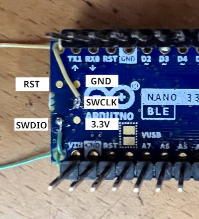
You can debug an application on the board with a debug adapter that supports CMSIS-DAP. This board has the SWD connector for debugging but exposes it as a test pad pattern (not a connector) on the back side of the PCB. So, It needs bit of difficult soldering. At a minimum, SWDIO and SWCLK need soldering (As shown in the picture). GND, 3.3V, and RESET are also available in the DIP connector, therefore it may be easier to connect using the DIP connector instead of soldering to them.
After connecting the debug adapter, you can debug it the usual way. Type the following command will start debugging.
# From the root of the zephyr repository
west build -b arduino_nano_33_ble samples/basic/blinky
west debug
Debugging with TRACE32 (GDB Front-End)
Lauterbach provides GDB Debug version TRACE32 for Arduino Nano 33 BLE [5]. That license ties to Arduino Nano 33 BLE hardware serial number, it also works with the ZephyrRTOS.
Follow the instruction of the tutorial for Arduino Lauterbach TRACE32 GDB Front-End Debugger for Nano 33 BLE [6] to install the TRACE32.
After installing the TRACE32, You should set the environmental variable T32_DIR.
If you installed TRACE32 into the home directory, run the following command.
(It is a good idea to put in the login script.)
export T32_DIR="~/T32Arduino"
The TRACE32 is TRACE32 as GDB Front-End [7] version. Required to run the GDB server before launching TRACE32 with the following command.
west build -b arduino_nano_33_ble samples/basic/blinky
west debugserver
Execute the following command after launching the GDB server to run the TRACE32 and connect the GDB server.
west debug --runner=trace32 -- gdbRemote=:3333
The TRACE32 script handles arguments after the -- sign.
You can set the following options.
Name |
Required? |
Description |
gdbRemote |
Required |
Set the GDB server address or device file of the serial port.
It can take <hostname>:<port> or <devicename>.
e.g.)
gdbRemote=localhost:3333, gdbRemote=/dev/ttyACM0 |
terminal |
Optional |
Set the device file of the serial port connected to the target console.
e.g.)
terminal=/dev/ttyACM1 |
userScript |
Optional |
Set user script that runs after system script execute done.
e.g.)
userScript="./user.cmm" |