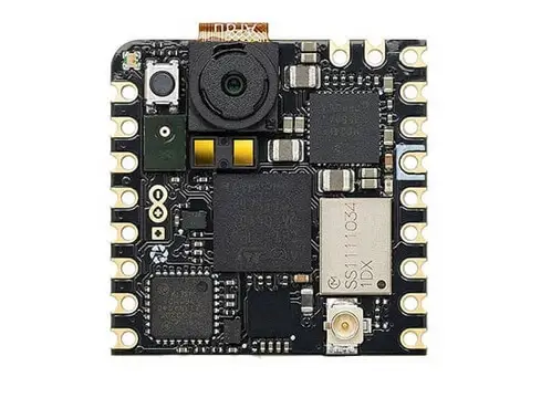
Arduino Nicla Vision
Overview
Arduino Nicla Vision is a development board by Arduino based on the STM32H747GAII, a dual core ARM Cortex-M7 + Cortex-M4 MCU, with 2MBytes of Flash memory and 1MB SRAM.
The board features:
RGB LED
Reset Boot button
USB device
Murata Type 1DX Bluetooth + WiFi module (CYW4343W based)
GC2145 2 Megapixel Camera Sensor
SE050C2HQ1 Crypto IC
MP34DT06JTR Omnidirectional Microphone
VL53L1CBV0FY ToF Sensor
LSM6DSOXTR Gyro+Accelerometer Sensor
More information about the board, including the datasheet, pinout and schematics, can be found at the Arduino Nicla Vision website.
More information about STM32H747GAII6 can be found here:
Supported Features
The arduino_nicla_vision board supports the hardware features listed below.
- on-chip / on-board
- Feature integrated in the SoC / present on the board.
- 2 / 2
-
Number of instances that are enabled / disabled.
Click on the label to see the first instance of this feature in the board/SoC DTS files. -
vnd,foo -
Compatible string for the Devicetree binding matching the feature.
Click on the link to view the binding documentation.
arduino_nicla_vision/stm32h747xx/m4 target
On-target memory for this board target: 128 KiB of RAM, 1 MiB of Flash.
Type |
Location |
Description |
Compatible |
|---|---|---|---|
CPU |
on-chip |
ARM Cortex-M4F CPU1 |
|
ADC |
on-chip |
STM32 ADC4 |
|
Audio |
on-chip |
STMicroelectronics DFSDM block1 |
|
on-chip |
STMicroelectronics DFSDM DMIC4 |
||
CAN |
on-chip |
STM32H7 series (and compatible) FDCAN CAN FD controller2 |
|
Clock control |
on-chip |
STM32H7 RCC (Reset and Clock controller)1 |
|
on-chip |
STM32 HSE Clock1 |
||
on-chip |
STM32 HSI Clock1 |
||
on-chip |
Generic fixed-rate clock provider3 |
||
on-chip |
STM32 LSE Clock1 |
||
on-chip |
STM32H7 main PLL3 |
||
on-chip |
STM32 Clock multiplexer1 |
||
on-chip |
STM32 Microcontroller Clock Output (MCO)2 |
||
Comparator |
on-chip |
STM32H7 series Comparator2 |
|
Counter |
on-chip |
STM32 counters14 |
|
CRC |
on-chip |
STM32 CRC calculation unit1 |
|
DAC |
on-chip |
STM32 family DAC1 |
|
Display |
on-chip |
STM32 LCD-TFT display controller1 |
|
DMA |
on-chip |
STM32 DMA controller (V1)2 |
|
on-chip |
STM32 BDMA controller1 |
||
on-chip |
STM32 DMAMUX controller2 |
||
Ethernet |
on-chip |
STM32H7 Ethernet1 |
|
on-chip |
STM32 MDIO Controller1 |
||
Flash controller |
on-chip |
STM32 Family flash controller1 |
|
GPIO & Headers |
on-chip |
STM32 GPIO Controller11 |
|
I2C |
on-chip |
STM32 I2C V2 controller4 |
|
I2S |
on-chip |
STM32H7 I2S controller3 |
|
on-chip |
STM32 SAI Block controller1 |
||
Interrupt controller |
on-chip |
ARMv7-M NVIC (Nested Vectored Interrupt Controller)1 |
|
on-chip |
STM32 External Interrupt Controller1 |
||
IPM |
on-chip |
STM32 HSEM MAILBOX1 |
|
LED |
on-board |
Group of GPIO-controlled LEDs1 |
|
Memory controller |
on-chip |
STM32 Battery Backed RAM1 |
|
on-chip |
STM32H7 Flexible Memory Controller (FMC)1 |
||
on-chip |
STM32 Flexible Memory Controller (SDRAM controller)1 |
||
MIPI-DSI |
on-chip |
STM32 MIPI DSI host1 |
|
MMC |
on-chip |
||
MTD |
on-chip |
STM32 flash memory1 |
|
NVMEM |
on-chip |
Fixed layout for Non-Volatile memory1 |
|
OTP memory |
on-chip |
STM32 embedded NVM OTP1 |
|
PHY |
on-chip |
This binding is to be used by all the usb transceivers which are built-in with USB IP1 |
|
Pin control |
on-chip |
STM32 Pin controller1 |
|
Power management |
on-chip |
STM32H7 power controller1 |
|
PWM |
on-chip |
STM32 PWM12 |
|
QSPI |
on-chip |
STM32 QSPI Controller1 |
|
Reset controller |
on-chip |
STM32 Reset and Clock Control (RCC) Controller1 |
|
RNG |
on-chip |
STM32 Random Number Generator1 |
|
RTC |
on-chip |
STM32 RTC1 |
|
Sensors |
on-chip |
STM32 quadrature decoder6 |
|
on-chip |
STM32 family TEMP node for production calibrated sensors with two calibration temperatures1 |
||
on-chip |
STM32 VBAT1 |
||
on-chip |
STM32 VREF+1 |
||
Serial controller |
on-chip |
STM32 USART4 |
|
on-chip |
|||
on-chip |
STM32 LPUART1 |
||
SMbus |
on-chip |
STM32 SMBus controller4 |
|
SPI |
on-chip |
STM32H7 SPI controller6 |
|
Timer |
on-chip |
ARMv7-M System Tick1 |
|
on-chip |
STM32 timers14 |
||
on-chip |
STM32 low-power timer (LPTIM)1 |
||
USB |
on-chip |
STM32 OTGHS controller1 |
|
on-chip |
STM32 OTGFS controller1 |
||
Video |
on-chip |
STM32 DCMI1 |
|
on-chip |
STM32 JPEG HW Codec1 |
||
Watchdog |
on-chip |
STM32 watchdog1 |
|
on-chip |
STM32 system window watchdog1 |
||
Wi-Fi |
on-board |
AIROC Wi-Fi Connectivity over SPI1 |
arduino_nicla_vision/stm32h747xx/m7 target
On-target memory for this board target: 512 KiB of RAM, 1 MiB of Flash.
Type |
Location |
Description |
Compatible |
|---|---|---|---|
CPU |
on-chip |
ARM Cortex-M7 CPU1 |
|
ADC |
on-chip |
STM32 ADC4 |
|
Audio |
on-chip |
STMicroelectronics DFSDM block1 |
|
on-chip |
|||
Bluetooth |
on-board |
Connectivity chip that uses Infineon Bluetooth Host Controller Interface UART driver1 |
|
CAN |
on-chip |
STM32H7 series (and compatible) FDCAN CAN FD controller2 |
|
Clock control |
on-chip |
STM32H7 RCC (Reset and Clock controller)1 |
|
on-board |
An external clock signal driven by a PWM pin1 |
||
on-chip |
STM32 HSE Clock1 |
||
on-chip |
STM32 HSI Clock1 |
||
on-chip |
|||
on-chip |
STM32 LSE Clock1 |
||
on-chip |
|||
on-chip |
STM32 Clock multiplexer1 |
||
on-chip |
STM32 Microcontroller Clock Output (MCO)2 |
||
Comparator |
on-chip |
STM32H7 series Comparator2 |
|
Counter |
on-chip |
STM32 counters14 |
|
CRC |
on-chip |
STM32 CRC calculation unit1 |
|
DAC |
on-chip |
STM32 family DAC1 |
|
Display |
on-chip |
STM32 LCD-TFT display controller1 |
|
DMA |
on-chip |
||
on-chip |
STM32 BDMA controller1 |
||
on-chip |
|||
Ethernet |
on-chip |
STM32H7 Ethernet1 |
|
on-chip |
STM32 MDIO Controller1 |
||
Flash controller |
on-chip |
STM32 Family flash controller1 |
|
on-board |
STM32 QSPI Flash controller supporting the JEDEC CFI interface1 |
||
GPIO & Headers |
on-chip |
STM32 GPIO Controller11 |
|
I2C |
on-chip |
||
I2S |
on-chip |
STM32H7 I2S controller3 |
|
on-chip |
STM32 SAI Block controller1 |
||
Interrupt controller |
on-chip |
ARMv7-M NVIC (Nested Vectored Interrupt Controller)1 |
|
on-chip |
STM32 External Interrupt Controller1 |
||
IPM |
on-chip |
STM32 HSEM MAILBOX1 |
|
LED |
on-board |
Group of GPIO-controlled LEDs1 |
|
Memory controller |
on-chip |
STM32 Battery Backed RAM1 |
|
on-chip |
STM32H7 Flexible Memory Controller (FMC)1 |
||
on-chip |
STM32 Flexible Memory Controller (SDRAM controller)1 |
||
MIPI-DSI |
on-chip |
STM32 MIPI DSI host1 |
|
MMC |
on-chip |
||
MMU / MPU |
on-chip |
ARMv7-M Memory Protection Unit (MPU)1 |
|
MTD |
on-chip |
STM32 flash memory1 |
|
on-chip |
Fixed partitions of a flash (or other non-volatile storage) memory1 |
||
NVMEM |
on-chip |
Fixed layout for Non-Volatile memory1 |
|
OTP memory |
on-chip |
STM32 embedded NVM OTP1 |
|
PHY |
on-chip |
This binding is to be used by all the usb transceivers which are built-in with USB IP1 |
|
on-board |
This binding is to be used by all the usb transceivers which are an external ULPI phy1 |
||
Pin control |
on-chip |
STM32 Pin controller1 |
|
Power management |
on-chip |
STM32H7 power controller1 |
|
PWM |
on-chip |
||
QSPI |
on-chip |
STM32 QSPI Controller1 |
|
Reset controller |
on-chip |
STM32 Reset and Clock Control (RCC) Controller1 |
|
RNG |
on-chip |
STM32 Random Number Generator1 |
|
RTC |
on-chip |
STM32 RTC1 |
|
Sensors |
on-board |
STMicroelectronics VL53L1X Time of Flight sensor1 |
|
on-board |
STMicroelectronics LSM6DSO 6-axis IMU (Inertial Measurement Unit) sensor accessed through I2C bus1 |
||
on-chip |
STM32 quadrature decoder6 |
||
on-chip |
STM32 family TEMP node for production calibrated sensors with two calibration temperatures1 |
||
on-chip |
STM32 VBAT1 |
||
on-chip |
STM32 VREF+1 |
||
Serial controller |
on-chip |
||
on-chip |
STM32 UART4 |
||
on-chip |
STM32 LPUART1 |
||
SMbus |
on-chip |
STM32 SMBus controller4 |
|
SPI |
on-chip |
||
Timer |
on-chip |
ARMv7-M System Tick1 |
|
on-chip |
|||
on-chip |
STM32 low-power timer (LPTIM)1 |
||
USB |
on-chip |
STM32 OTGHS controller1 |
|
on-chip |
STM32 OTGFS controller1 |
||
Video |
on-board |
Galaxy Core GC2145 CMOS video sensor1 |
|
on-chip |
STM32 DCMI1 |
||
on-chip |
STM32 JPEG HW Codec1 |
||
Watchdog |
on-chip |
STM32 watchdog1 |
|
on-chip |
STM32 system window watchdog1 |
||
Wi-Fi |
on-board |
AIROC Wi-Fi Connectivity over SPI1 |
Fetch Binary Blobs
The board Bluetooth/WiFi module requires fetching some binary blob files, to do that run the command:
west blobs fetch hal_infineon
Resources sharing
The dual core nature of STM32H747 SoC requires sharing HW resources between the two cores. This is done in 3 ways:
Compilation: Clock configuration is only accessible to M7 core. M4 core only has access to bus clock activation and deactivation.
Static pre-compilation assignment: Peripherals such as a UART are assigned in devicetree before compilation. The user must ensure peripherals are not assigned to both cores at the same time.
Run time protection: Interrupt-controller and GPIO configurations could be accessed by both cores at run time. Accesses are protected by a hardware semaphore to avoid potential concurrent access issues.
Programming and Debugging
The arduino_nicla_vision board supports the runners and associated west commands listed below.
| flash | debug | attach | debugserver | rtt | reset | |
|---|---|---|---|---|---|---|
| blackmagicprobe | ✅ | ✅ (default) | ✅ | |||
| dfu-util | ✅ (default) | |||||
| jlink | ✅ | ✅ | ✅ | ✅ | ✅ | ✅ |
| openocd | ✅ | ✅ | ✅ | ✅ | ✅ |
Applications for the arduino_nicla_vision board should be built per core target,
using either arduino_nicla_vision/stm32h747xx/m7 or arduino_nicla_vision/stm32h747xx/m4 as the target.
See Building an Application for more information about application builds.
Flashing
This board can be flashed either using dfu-util, or with an external debugging probe, such as a J-Link or Black Magic Probe, connected to the on board MIPI-10 SWD port marked as “JTAG”.
Note
The board ships with a custom Arduino bootloader programmed in the first
flash page that can be triggered by double clicking the RST button. This
bootloader is USB-DFU compatible and supports programming both the internal
and external flash and is the one used by west flash by default.
First, connect the Arduino Nicla Vision board to your host computer using the USB
port to prepare it for flashing. Double click the RST button to put the
board into the Arduino Bootloader mode. Then build and flash your application.
Here is an example for the Hello World application.
# From the root of the zephyr repository
west build -b arduino_nicla_vision/stm32h747xx/m7 samples/hello_world
west flash
Run a serial host program to connect with your board:
$ minicom -D /dev/ttyACM0
You should see the following message on the console:
Hello World! arduino_nicla_vision
Similarly, you can build and flash samples on the M4 target.
Here is an example for the Blinky application on M4 core.
# From the root of the zephyr repository
west build -b arduino_nicla_vision/stm32h747xx/m4 samples/basic/blinky
west flash
Debugging
Debugging is supported by using west debug with an external probe such as a
J-Link or Black Magic Probe, connected to the on board through the edge eslov pins
as “SWD”. For example:
west debug -r jlink