SixG301 Explorer Kit (BRD2719A)
Overview
The SixG301 Explorer Kit (BRD2719A) is a development platform based on the Silicon Labs SIMG301M104LIL wireless SoC. It supports the development of 2.4 GHz wireless IoT applications.
The kit provides an on-board SEGGER J-Link debugger, a USB virtual COM port, two user LEDs, two push buttons, GPIO breakout pads, a mikroBUS socket and a Qwiic connector.
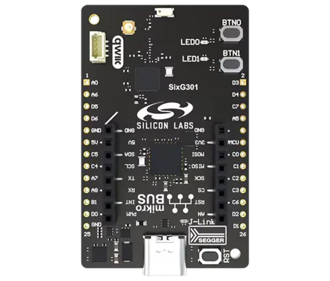
Hardware
SoC: SIMG301M104LIL
CPU: Arm Cortex-M33 with FPU
Maximum CPU frequency: 150 MHz
Flash: 4 MB physical flash
RAM: 512 KB
Wireless frequency: 2.4 GHz
On-board SEGGER J-Link debugger and USB virtual COM port
mikroBUS socket and Qwiic connector
Supported Features
The sixg301_ek2719a board supports the hardware features listed below.
- on-chip / on-board
- Feature integrated in the SoC / present on the board.
- 2 / 2
-
Number of instances that are enabled / disabled.
Click on the label to see the first instance of this feature in the board/SoC DTS files. -
vnd,foo -
Compatible string for the Devicetree binding matching the feature.
Click on the link to view the binding documentation.
sixg301_ek2719a/simg301m104lil target
On-target memory for this board target: 512 KiB of RAM, 3652 KiB of Flash.
Type |
Location |
Description |
Compatible |
|---|---|---|---|
CPU |
on-chip |
ARM Cortex-M33 CPU1 |
|
ADC |
on-chip |
Silicon Labs Series 3 ADC1 |
|
Bluetooth |
on-chip |
Silicon Labs Series 2 Bluetooth HCI1 |
|
Clock control |
on-chip |
Silicon Labs Series 2 HFRCOEM231 |
|
on-chip |
Silicon Labs Series 2 HFXO1 |
||
on-chip |
Silicon Labs SOCPLL1 |
||
on-chip |
Silicon Labs Series 2 CMU1 |
||
on-chip |
Silicon Labs CMU CLKOUT1 |
||
on-chip |
Silicon Labs Series 2 HFRCODPLL1 |
||
on-chip |
Generic fixed-rate clock provider3 |
||
on-chip |
Silicon Labs Series 2 LFXO1 |
||
on-chip |
Silicon Labs Series 2 LFRCO1 |
||
on-chip |
Generic fixed factor clock provider24 |
||
Comparator |
on-chip |
Silicon Labs Series 2 ACMP2 |
|
Counter |
on-chip |
Silicon Labs TIMER Counter4 |
|
on-chip |
Silicon Labs Series 2 BURTC1 |
||
on-chip |
Silicon Labs PROTIMER counter1 |
||
CRC |
on-chip |
Silabs General Purpose CRC1 |
|
Cryptographic accelerator |
on-chip |
||
on-chip |
Silicon Labs Series 2 SE Mailbox1 |
||
Debug |
on-chip |
Silicon Labs Packet Trace Interface1 |
|
on-chip |
ARMv8 instrumentation trace macrocell1 |
||
DMA |
on-chip |
Silicon Labs Series 2 LDMA1 |
|
Flash controller |
on-chip |
Silicon Labs Series 3 EXTMEM1 |
|
GPIO & Headers |
on-chip |
Silicon Labs Series 2 GPIO Peripheral1 |
|
on-chip |
Silicon Labs Series 2 GPIO Port4 |
||
on-board |
STEMMA QT is a 4-pin JST-SH connector for I2C devices1 |
||
on-board |
GPIO pins exposed on Mikro BUS headers1 |
||
I2C |
on-chip |
||
IEEE 802.15.4 |
on-chip |
Silicon Labs EFR32 IEEE 802.15.4 radio1 |
|
Input |
on-board |
Group of GPIO-bound input keys1 |
|
Interrupt controller |
on-chip |
ARMv8-M NVIC (Nested Vectored Interrupt Controller)1 |
|
LED |
on-board |
Group of GPIO-controlled LEDs1 |
|
MMU / MPU |
on-chip |
ARMv8-M MPU (Memory Protection Unit)1 |
|
MTD |
on-chip |
Flash node1 |
|
Networking |
on-chip |
Silicon Labs Series 2 Radio Interface1 |
|
Pin control |
on-chip |
Silicon Labs Series 2 DBUS Pin Controller1 |
|
PWM |
on-chip |
Silicon Labs LETIMER PWM1 |
|
on-chip |
Silicon Labs TIMER PWM4 |
||
Retained memory |
on-chip |
Silicon Labs Series 2 BURAM1 |
|
RTC |
on-chip |
Silicon Labs Series 2 SYSRTC1 |
|
Serial controller |
on-chip |
Silicon Labs Series 2 EUSART 1 |
|
SPI |
on-chip |
||
SRAM |
on-chip |
Generic on-chip SRAM1 |
|
Timer |
on-chip |
ARMv8-M System Tick1 |
|
on-chip |
Silicon Labs LETIMER1 |
||
on-chip |
Silicon Labs TIMER4 |
||
Watchdog |
on-chip |
System Clock
The system clock uses the SoC PLL configured for 150 MHz.
Serial Port
EUSART0 is used for the console. The default pin configuration is:
TX: PB2
RX: PB0
The default console settings are 115200 baud, 8 data bits, no parity and 1 stop bit.
I2C
The default I2C0 pin configuration is:
SDA: PC5
SCL: PC4
Both pins are configured for open-drain operation with pull-up resistors.
Programming and Debugging
The sixg301_ek2719a board supports the runners and associated west commands listed below.
| flash | debug | rtt | reset | attach | debugserver | |
|---|---|---|---|---|---|---|
| jlink | ✅ | ✅ (default) | ✅ | ✅ | ✅ | ✅ |
| silabs_commander | ✅ (default) |
Memory Configuration
The SiMG301 flash controller divides memory into 8 code regions and one data region. Code regions are made up of 32 kB erasable pages used to store firmware images. The data region is made up of 4 kB erasable pages used to store data.
Code regions may be configured with no protection, EXiP (encrypted execute-in-place) or AXiP (authenticated execute-in-place). When AXiP is enabled, an additional 4 bytes of MAC (message authentication code) are stored for every 32 bytes of ciphertext. This means that 36 kB of physical memory is consumed for every 32 kB of firmware. The MAC is not directly accessible, but must be accounted for when calculating code and data region sizes. See Configuring Code Regions for more information.
In Zephyr, the partition configuration in Devicetree must align with the logical memory map as configured on the device. Since the apparent logical size of memory varies depending on how many flash pages are used for AXiP code regions, the total flash size must also be configured to match the device configuration.
Configuring the Board for Development
When AXiP (authenticated execute-in-place) or EXiP (encrypted execute-in-place) are enabled, it is recommended to configure development devices to not regenerate the IV (initial value) for flash encryption every time an image is flashed, to limit the use of OTP (one-time-programmable memory) bits.
This can be done by executing the following command using Simplicity Commander:
commander security transitiontodevelopment
See Considerations for Development Devices for more details. For more information about OTP bit consumption, see SE Anti-Rollback OTP Bit Consumption for Series 3.
Flashing
Connect the BRD2719A Explorer Kit to the host computer using its USB connector.
Build and flash the Hello World sample:
# From the root of the zephyr repository
west build -b sixg301_ek2719a samples/hello_world
west flash
Open a serial terminal connected to the board’s virtual COM port with these settings:
Baud rate: 115200
Data bits: 8
Parity: None
Stop bits: 1
After resetting the board, the terminal should display:
Hello World! sixg301_ek2719a/simg301m104lil
Bluetooth
To use Bluetooth functionality, run the command below to retrieve necessary binary blobs from the Silicon Labs HAL repository.
west blobs fetch hal_silabs
Then build the Zephyr kernel and a Bluetooth sample with the following command. The Observer sample application is used in this example.
# From the root of the zephyr repository
west build -b sixg301_ek2719a samples/bluetooth/observer
west flash
Debugging
The board provides an on-board SEGGER J-Link debugger. west flash uses
Simplicity Commander by default, and west debug uses J-Link.