RZ/A3UL SMARC Evaluation Board Kit
Overview
The Renesas RZ/A3UL SMARC Evaluation Board Kit (RZ/A3UL-EVKIT) consists of a SMARC v2.1 module board and a carrier board. Two types of evaluation boards are available: QSPI version and Octal-SPI version. The QSPI version is supported.
Device: RZ/A3UL R9A07G063U02GBG
Cortex-A55 Single
BGA361pin, 13mmSq body, 0.5mm pitch
Certified device in Azure Certified Device Catalog
SMARC v2.1 Module Board Functions
Two types of evaluation boards are available:
QSPI version: QSPI Serial Flash (Boot) + DDR4
Octal-SPI version: Octa Flash (Boot) + OctaRAM + DDR4
DDR4 SDRAM: 1GB x 1pc
QSPI flash memory: 128Mb x 1pc AT25QL128A (QSPI version)
Octa RAM memory: 512Mb x 1pc / Octa flash memory: 1Gb x 1pc (Octal-SPI version)
eMMC memory: 64GB x 1pc
The microSD card slot is implemented and used as an eSD for boot.
5-output clock oscillator 5P35023 implemented
PMIC power supply DA9062 implemented
Carrier Board Functions
The FFC/FPC connector is mounted as standard for connection to high-speed serial interface for camera module.
The Micro-HDMI connector via DSI/HDMI conversion module is mounted as standard for connection to high-speed serial interface for digital video module.
The Micro-AB receptacle (ch0: USB2.0 OTG) and A receptacle (ch1: USB2.0 Host) are respectively mounted as standard for connection to USB interface.
The RJ45 connector is mounted as standard for software development and evaluation using Ethernet.
The audio codec is mounted as standard for advance development of audio system. The audio jack is implemented for connection to audio interface.
The Micro-AB receptacles are implemented for connection to asynchronous serial port interface.
The microSD card slot and two sockets for PMOD are implemented as an interface for RZ/A3UL peripheral functions.
For power supply, a mounted USB Type-C receptacle supports the USB PD standard.
Hardware
The Renesas RZ/A3UL MPU documentation can be found at RZ/A3UL Group Website [1]
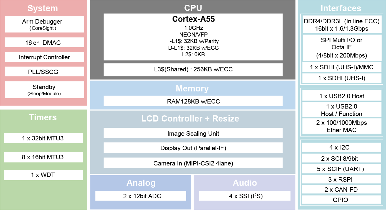
RZ/A3UL block diagram (Credit: Renesas Electronics Corporation)
Detailed hardware features for the board can be found at RZA3UL-EVKIT Website [2]
Supported Features
The rza3ul_smarc board supports the hardware features listed below.
- on-chip / on-board
- Feature integrated in the SoC / present on the board.
- 2 / 2
-
Number of instances that are enabled / disabled.
Click on the label to see the first instance of this feature in the board/SoC DTS files. -
vnd,foo -
Compatible string for the Devicetree binding matching the feature.
Click on the link to view the binding documentation.
rza3ul_smarc/r9a07g063u02gbg target
On-target memory for this board target: 1022 MiB of RAM, 16 MiB of Flash.
Type |
Location |
Description |
Compatible |
|---|---|---|---|
CPU |
on-chip |
ARM Cortex-A55 CPU1 |
|
ADC |
on-chip |
Renesas RZ ADC-C driver1 |
|
Clock control |
on-chip |
Renesas RZ Clock Pulse Generator1 |
|
on-chip |
Renesas RZ Clock Pulse Generator PLL Output10 |
||
on-chip |
Renesas RZ Clock Pulse Generator Clock Output19 |
||
on-chip |
Generic fixed-rate clock provider1 |
||
Counter |
on-chip |
Renesas RZ GTM Counter3 |
|
DMA |
on-chip |
RZ DMA controller1 |
|
Flash controller |
on-board |
Renesas RZ SPIBSC NOR FLASH supporting the JEDEC CFI interface1 |
|
GPIO & Headers |
on-chip |
Renesas RZ GPIO common1 |
|
on-chip |
Renesas RZ GPIO controller19 |
||
I2C |
on-chip |
||
Interrupt controller |
on-chip |
ARM Generic Interrupt Controller v31 |
|
on-chip |
Renesas RZ Interrupt Controller1 |
||
on-chip |
Renesas RZ external interrupt controller9 |
||
on-chip |
Renesas RZ GPIO interrupt (TINT) controller32 |
||
MTD |
on-board |
Fixed partitions of a flash (or other non-volatile storage) memory1 |
|
Pin control |
on-chip |
Below generic example shows of supported pinctrl definitions:1 |
|
PWM |
on-chip |
Renesas RZ Multi-Function Timer Pulse Unit (MTU) PWM Controller7 |
|
QSPI |
on-chip |
Renesas RZ SPIBSC1 |
|
Serial controller |
on-chip |
||
SPI |
on-chip |
||
Timer |
on-chip |
Renesas RZ MTU controller7 |
|
on-chip |
Renesas RZ GTM Timer3 |
||
on-chip |
Renesas RZ OS timer3 |
||
on-chip |
per-core ARM architected timer1 |
||
Watchdog |
on-chip |
Renesas RZ Watchdog (wdt)1 |
Programming and Debugging
The rza3ul_smarc board supports the runners and associated west commands listed below.
| flash | debug | reset | attach | rtt | debugserver | |
|---|---|---|---|---|---|---|
| jlink | ✅ (default) | ✅ (default) | ✅ | ✅ | ✅ | ✅ |
RZ/A3UL-EVKIT uses Initial Program Loader (IPL) to perform initial settings and copy the Zephyr image from flash to DDR SRAM for execution. It only needs to be written to flash once.
There are two options to write IPL:
(Recommended) Follow ‘’4. Tutorial: Your First RZ MPU Project - Blinky’’ of Getting Started with RZ/A Flexible Software Package [4] to start writing a blinky sample with FSP. The IPL will be written to flash by default in debugging time.
Follow the Initial Program Loader Application Note [3] to write the IPL separately. The minimal steps are described below.
Follow ‘’6. IPL development environment construction procedure’’ to prepare the build environment.
Follow ‘’7. IPL build environment construction procedure’’ to build Initial Program Loader. If the build is successful, Initial Program Loader file will be generated in /build/a3ul/release/rza3ul_smarc_qspi_ipl.srec
Follow ‘’8.1 Create Debug Configuration’’ to create a Debug configuration to run Initial Program Loader on the target board.
Follow ‘’8.2 Connection to SMARC EVK Board’’ to setup target board with SW1 Debugger Enable (SW1-1 OFF) and Boot (1.8V) Mode (SW11[1:4]=OFF OFF OFF ON).
Follow ‘’8.4 Execution procedure of IPL’’ to write Initial Program Loader to the target board.
Applications for the rza3ul_smarc board can be built in the usual way as
documented in Building an Application.
Console
The UART port is accessed by USB Type-mircoB port (CN14).
Debugging
It is possible to load and execute a Zephyr application binary on this board on the Cortex-A55 System Core
from the DDR SDRAM, using JLink debugger (J-Link Debug Host Tools).
Here is an example for building and debugging with the Hello World application.
# From the root of the zephyr repository
west build -b rza3ul_smarc samples/hello_world
west debug
Flashing
Zephyr application can be flashed to QSPI/Octal-SPI storage and then loaded by Initial Program Loader.
# From the root of the zephyr repository
west build -b rza3ul_smarc samples/hello_world
west flash