Renesas Starter Kit+ for RZ/N2L
Overview
Renesas Starter Kit+ for RZ/N2L is for evaluation or development using the RZ/N2L MPU. With the on-board emulator, you can start evaluation by simply connecting the bundled cable with your PC. This product has rich functional ICs such as Gigabit Ethernet PHY and Octal Flash, you can fully evaluate functions without an extension board.
On-board RZ/N2L MPU 225-pin (R9A07G084M04GBG)
Rich functional ICs such as Gigabit Ethernet PHY and Octal Flash are mounted, so functions of target MPU can be fully evaluated
Generic interfaces such as Pmod/Grove/Qwiic/mikroBUS
Pin headers for external extension enable you to evaluate many use cases
Emulator circuit is mounted, and program debugging can be started by simply connecting USB cable to PC (two USB cables are included, one for emulator and the other for power supply)
On-board memory components:
SDRAM (256MBit)
NOR Flash (256MBit)
Octa Flash (512MBit)
HyperRAM (64Mbit)
QSPI Serial Flash (512Mbit)
I2C EEPROM (32Kbit)
Communication interfaces include:
Debug interfaces (J-Link OB, MIPI-10, MIPI-20)
Ethernet
CAN
USB
RS485
UART
I2C
SPI
Hardware
The Renesas RZ/N2L MPU documentation can be found at RZ/N2L Group Website [1]

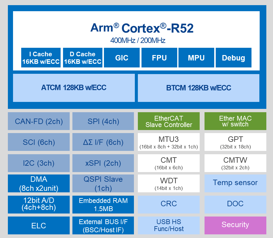
RZ/N2L block diagram (Credit: Renesas Electronics Corporation)
Detailed hardware features for the board can be found at RZ/N2L-RSK Website [2]
Supported Features
The rzn2l_rsk board supports the hardware features listed below.
- on-chip / on-board
- Feature integrated in the SoC / present on the board.
- 2 / 2
-
Number of instances that are enabled / disabled.
Click on the label to see the first instance of this feature in the board/SoC DTS files. -
vnd,foo -
Compatible string for the Devicetree binding matching the feature.
Click on the link to view the binding documentation.
rzn2l_rsk/r9a07g084m04gbg target
Type |
Location |
Description |
Compatible |
|---|---|---|---|
CPU |
on-chip |
ARM Cortex-R52 CPU1 |
|
ADC |
on-chip |
Renesas RZ ADC2 |
|
Clock control |
on-chip |
Renesas RZ Clock Generator Circuit1 |
|
on-chip |
Generic fixed-rate clock provider2 |
||
on-chip |
Renesas RZ Clock Generator Circuit PLL Clock1 |
||
on-chip |
Renesas RZ Clock Control System Clock3 |
||
on-chip |
Renesas RZ Clock Control Peripheral Sub-Clock14 |
||
Counter |
on-chip |
Renesas RZ CMTW Counter2 |
|
DMA |
on-chip |
RZ DMA controller2 |
|
Flash controller |
on-board |
Renesas RZ XSPI NOR FLASH supporting the JEDEC CFI interface1 |
|
GPIO & Headers |
on-chip |
Renesas RZ GPIO common V21 |
|
on-chip |
|||
I2C |
on-chip |
||
Input |
on-board |
Group of GPIO-bound input keys1 |
|
Interrupt controller |
on-chip |
ARM Generic Interrupt Controller v31 |
|
on-chip |
Renesas RZ Interrupt Controller (ICU)1 |
||
on-chip |
|||
LED |
on-board |
Group of GPIO-controlled LEDs1 |
|
Miscellaneous |
on-chip |
||
MTD |
on-chip |
Fixed partitions of a flash (or other non-volatile storage) memory1 |
|
Pin control |
on-chip |
Renesas RZ/T pin controller1 |
|
PWM |
on-chip |
Renesas RZ GPT PWM18 |
|
QSPI |
on-chip |
||
Serial controller |
on-chip |
||
SPI |
on-chip |
||
SRAM |
on-chip |
Generic on-chip SRAM4 |
|
Timer |
on-chip |
Renesas RZ GPT18 |
|
on-chip |
Renesas RZ CMTW Timer2 |
||
on-chip |
per-core ARM architected timer1 |
||
Watchdog |
on-chip |
Renesas RZ Watchdog (wdt)1 |
Connections and IOs
By default, the board is configured for use with:
UART0 connected to the USB serial port (pins H15, G11),
UART3 connected to the PMOD Header (J25, pins E14, E15),
LEDs defined as
led0,led1,led2andled3,
The Zephyr console uses UART0.
Programming and Debugging
The rzn2l_rsk board supports the runners and associated west commands listed below.
| flash | debug | attach | rtt | reset | debugserver | |
|---|---|---|---|---|---|---|
| jlink | ✅ (default) | ✅ (default) | ✅ | ✅ | ✅ | ✅ |
Applications for the rzn2l_rsk board can be
built, flashed, and debugged in the usual way. See Building an Application
and Run an Application for more details on building and running.
To use J-Link OB on RSK+RZN2L,
Open the jumper pin (J9) for switching the debug connection.
Connect the micro-USB type-B to J-Link OB USB connector (J10), and then the LED4 is lighted.
Console
The UART port is accessed by USB-Serial port (CN16).
Debugging
Here is an example for building and debugging with the Hello World application.
# From the root of the zephyr repository
west build -b rzn2l_rsk samples/hello_world
west debug
Flashing
Before using flash command, the board must be set to xSPI boot mode.
# From the root of the zephyr repository
west build -b rzn2l_rsk samples/hello_world
west flash