XIAO STM32C5
Overview
The Seeed Studio XIAO STM32C5 is a compact development board based on the STM32C5A3CG SoC (Cortex-M33, 144 MHz, 256 KB SRAM, 1 MB flash). It offers the standard XIAO form factor with a 16-pin castellated connector exposing UART, I2C, SPI, ADC and two FDCAN buses, an on-board LSM6DSL IMU, a CAN transceiver, a user LED, a BOOT button, battery charging with a voltage-divider enable, and a USB-C connector for power, programming (TinyUF2 bootloader) and a CDC-ACM virtual serial port.
For more details see the Seeed Studio XIAO STM32C5 [1] board documentation and examples repository.
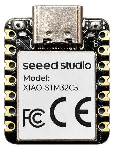
Hardware
The board is based on the STM32C5A3CG SoC in a UFQFPN48 package:
ARM Cortex-M33 with FPU, up to 144 MHz
1 MB flash, 256 KB SRAM
XSPI1 with an on-board 16 MB Puya PY25Q128HA NOR flash (external flash support will be enabled on top of the MSPI framework)
USB 2.0 full-speed device/controller
Supported Features
The xiao_stm32c5 board supports the hardware features listed below.
- on-chip / on-board
- Feature integrated in the SoC / present on the board.
- 2 / 2
-
Number of instances that are enabled / disabled.
Click on the label to see the first instance of this feature in the board/SoC DTS files. -
vnd,foo -
Compatible string for the Devicetree binding matching the feature.
Click on the link to view the binding documentation.
xiao_stm32c5/stm32c5a3xx target
On-target memory for this board target: 256 KiB of RAM, 1 MiB of Flash.
Type |
Location |
Description |
Compatible |
|---|---|---|---|
CPU |
on-chip |
ARM Cortex-M33 CPU1 |
|
ADC |
on-chip |
||
CAN |
on-chip |
||
Clock control |
on-chip |
STM32C5 RCC.1 |
|
on-chip |
STM32 HSE Clock1 |
||
on-chip |
|||
on-chip |
|||
on-chip |
STM32 LSE Clock1 |
||
on-chip |
STM32 Clock multiplexer1 |
||
on-chip |
STM32 Microcontroller Clock Output (MCO)2 |
||
Counter |
on-chip |
STM32 counters12 |
|
CRC |
on-chip |
STM32 CRC calculation unit1 |
|
Cryptographic accelerator |
on-chip |
STM32 HASH Processor1 |
|
DAC |
on-chip |
STM32 family DAC1 |
|
DMA |
on-chip |
STM32U5 DMA controller2 |
|
Ethernet |
on-chip |
ST STM32 Ethernet MAC1 |
|
on-chip |
Synopsys DesignWare MAC MDIO controller1 |
||
on-chip |
Synopsys DesignWare MAC PTP (Precision Time Protocol) Clock1 |
||
Flash controller |
on-chip |
STM32 Family flash controller1 |
|
GPIO & Headers |
on-chip |
STM32 GPIO Controller8 |
|
on-board |
GPIO pins exposed on Seeeduino Xiao (and compatible devices) headers1 |
||
I2C |
on-chip |
STM32 I2C V2 controller2 |
|
I2S |
on-chip |
STM32H7 I2S controller3 |
|
I3C |
on-chip |
STM32H5 I3C controller1 |
|
Input |
on-board |
Group of GPIO-bound input keys1 |
|
Interrupt controller |
on-chip |
ARMv8-M NVIC (Nested Vectored Interrupt Controller)1 |
|
on-chip |
STM32G0 External Interrupt Controller1 |
||
LED |
on-board |
Group of GPIO-controlled LEDs2 |
|
on-board |
Group of PWM-controlled LEDs1 |
||
MMU / MPU |
on-chip |
ARMv8-M MPU (Memory Protection Unit)1 |
|
Multi-bit SPI |
on-chip |
STM32 XSPI controller1 |
|
MTD |
on-chip |
STM32 flash memory1 |
|
NVMEM |
on-chip |
Fixed layout for Non-Volatile memory1 |
|
OTP memory |
on-chip |
||
PHY |
on-chip |
This binding is to be used by all the usb transceivers which are built-in with USB IP1 |
|
on-board |
Simple GPIO controlled CAN transceiver1 |
||
Pin control |
on-chip |
STM32 Pin controller1 |
|
Power management |
on-chip |
STM32 power controller1 |
|
on-chip |
STM32 wake-up lines controller1 |
||
PWM |
on-chip |
||
Reset controller |
on-chip |
STM32 Reset and Clock Control (RCC) Controller1 |
|
RNG |
on-chip |
STM32 Random Number Generator1 |
|
RTC |
on-chip |
STM32 RTC1 |
|
Sensors |
on-chip |
STM32 quadrature decoder7 |
|
on-board |
STMicroelectronics LSM6DSL 6-axis accelerometer and gyrometer accessed through I2C bus1 |
||
on-chip |
STM32 family TEMP node for production calibrated sensors with two calibration temperatures1 |
||
on-chip |
STM32 VREF+1 |
||
Serial controller |
on-chip |
STM32 LPUART1 |
|
on-chip |
|||
on-chip |
STM32 UART3 |
||
SPI |
on-chip |
||
SRAM |
on-chip |
Generic on-chip SRAM1 |
|
Timer |
on-chip |
ARMv8-M System Tick1 |
|
on-chip |
STM32U5 LPTIM1 |
||
on-chip |
|||
USB |
on-chip |
STM32 USB controller1 |
|
Watchdog |
on-chip |
STM32 watchdog1 |
|
on-chip |
STM32 system window watchdog1 |
Connections and IOs
The board uses the standard XIAO pinout. Default mapping of D0-D15 is as follows:
D0 : PA0 (ADC1_IN0)
D1 : PA1 (ADC1_IN1)
D2 : PA2 (ADC1_IN2)
D3 : PA3 (ADC1_IN3)
D4 : PB7 (I2C1_SDA)
D5 : PB6 (I2C1_SCL)
D6 : PA9 (USART1_TX)
D7 : PA10 (USART1_RX)
D8 : PE2 (SPI3_SCK)
D9 : PB0 (SPI3_MISO)
D10 : PB15 (SPI3_MOSI)
D11 : PB8 (FDCAN1_RX)
D12 : PB9 (FDCAN1_TX)
D13 : PB5 (FDCAN2_RX)
D14 : PB13 (FDCAN2_TX)
D15 : PB14 (CAN transceiver standby)
On-board devices:
User LED: PB12 (active low)
BOOT button: PH2/BOOT0
LSM6DSL IMU: I2C2 (0x6A), interrupt on PC13
Battery voltage divider enable: PA15
CAN transceiver standby: PB14
Programming and Debugging
The xiao_stm32c5 board supports the runners and associated west commands listed below.
| flash | debug | |
|---|---|---|
| stm32cubeprogrammer | ✅ (default) |
Flashing
Using UF2
The board ships with the TinyUF2 bootloader. Build an application with
west build -b xiao_stm32c5 and copy the generated
build/zephyr/zephyr.uf2 to the XIAOSTM32C5 mass-storage device
that appears when the board is powered on with the BOOT button held (double
reset also enters the bootloader). The application is linked to start at
0x08008000 to coexist with the bootloader.
Using STM32CubeProgrammer
The board is configured to be flashed using west STM32CubeProgrammer [2] runner, so its installation is required. An external SWD probe (ST-LINK, J-Link, …) is needed; the SWD signals are exposed on the XIAO header footprint.
Debugging
Debugging with an external SWD probe (ST-LINK, J-Link, …) is supported in the usual way; the SWD signals are exposed on the XIAO header footprint.
Default configuration
The default console and shell use the USB CDC-ACM virtual serial port from
the common boards/common/usb fragments. Alternatively, USART1 is available
on the D6/D7 pins (PA9/PA10, 115200 8N1).