EVK-BMD-34/38: BMD-340-EVAL and BMD-341-EVAL
u-blox EVK-BMD-34/38: BMD-340-EVAL and BMD-341-EVAL
Overview
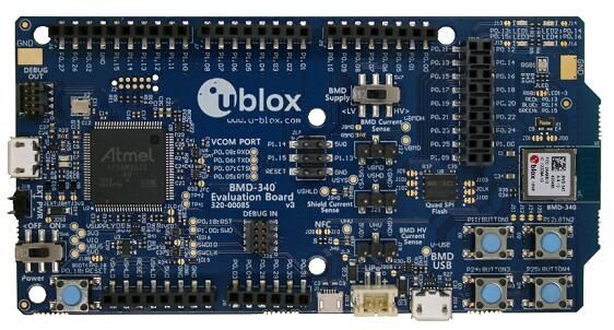
The BMD-340-EVAL and BMD-341-EVAL hardware provides support for the u-blox BMD-340 and BMD-341 Bluetooth 5.0 modules, based on the Nordic Semiconductor nRF52840 ARM Cortex-M4F CPU. the BMD-340 and BMD-341 are identical in operation except for the antenna. The BMD-340 has a PCB antenna while the BMD-341 has a U.FL connector. Both support the following devices:
ADC
CLOCK
FLASH
GPIO
I2C
MPU
NVIC
PWM
RADIO (Bluetooth Low Energy and 802.15.4)
RTC
Segger RTT (RTT Console)
SPI
UART
USB
WDT
More information about the BMD-340-EVAL, BMD-340 module, BMD-341-EVAL, and BMD-341 module can be found at the u-blox website [1]. All of the Nordic Semiconductor examples for the nRF52840 DK (nrf52840dk_nrf52840) may be used without modification.
- ..note::
The BMD-340 and BMD-341 are identical except for the antenna. Throughout this board support package, the filenames utilize the ubx_bmd340eval_nrf52840.
Hardware
The BMD-340 on the BMD-340-EVAL (or BMD-341 on the BMD-341-EVAL) contains an internal high-frequency oscillator at 32MHz. There is also a low frequency (slow) oscillator of 32.768kHz. The BMD-340 and BMD-341 do not include the slow crystal; however, the BMD-340-EVAL and BMD-341-EVAL do.
Note
When targeting a custom design without a slow crystal, be sure to modify code to utilize the internal RC oscillator for the slow clock.
Supported Features
The ubx_bmd340eval board supports the hardware features listed below.
- on-chip / on-board
- Feature integrated in the SoC / present on the board.
- 2 / 2
-
Number of instances that are enabled / disabled.
Click on the label to see the first instance of this feature in the board/SoC DTS files. -
vnd,foo -
Compatible string for the Devicetree binding matching the feature.
Click on the link to view the binding documentation.
ubx_bmd340eval/nrf52840 target
On-target memory for this board target: 256 KiB of RAM, 1 MiB of Flash.
Type |
Location |
Description |
Compatible |
|---|---|---|---|
CPU |
on-chip |
ARM Cortex-M4F CPU1 |
|
ADC |
on-chip |
Nordic Semiconductor nRF family SAADC node1 |
|
on-board |
ADC channels exposed on Arduino Uno (R3) headers1 |
||
ARM architecture |
on-chip |
Nordic UICR (User Information Configuration Registers)1 |
|
on-chip |
Nordic EGU (Event Generator Unit)6 |
||
on-chip |
Nordic nRF family ACL (Access Control List)1 |
||
on-chip |
Nordic nRF family MWU (Memory Watch Unit)1 |
||
Audio |
on-chip |
Nordic PDM (Pulse Density Modulation interface)1 |
|
Clock control |
on-chip |
Nordic nRF clock control node1 |
|
on-chip |
Nordic nRF high-frequency crystal oscillator (nRF52 series)1 |
||
Comparator |
on-chip |
Nordic nRF COMP (analog COMParator)1 |
|
Counter |
on-chip |
Nordic nRF timer node5 |
|
Cryptographic accelerator |
on-chip |
Nordic ECB (AES electronic codebook mode encryption)1 |
|
on-chip |
Nordic nRF family CCM (AES CCM mode encryption)1 |
||
on-chip |
ARM TrustZone CryptoCell 3101 |
||
Debug |
on-chip |
ARMv7 instrumentation trace macrocell1 |
|
Flash controller |
on-chip |
Nordic NVMC (Non-Volatile Memory Controller)1 |
|
on-chip |
Properties defining the interface for the Nordic QSPI peripheral1 |
||
GPIO & Headers |
on-chip |
NRF5 GPIOTE1 |
|
on-chip |
NRF5 GPIO2 |
||
on-board |
GPIO pins exposed on Arduino Uno (R3) headers1 |
||
I2C |
on-chip |
||
I2S |
on-chip |
Nordic I2S (Inter-IC sound interface)1 |
|
IEEE 802.15.4 |
on-chip |
Nordic nRF IEEE 802.15.4 node1 |
|
Input |
on-board |
Group of GPIO-bound input keys1 |
|
Interrupt controller |
on-chip |
ARMv7-M NVIC (Nested Vectored Interrupt Controller)1 |
|
LED |
on-board |
Group of GPIO-controlled LEDs1 |
|
on-board |
Group of PWM-controlled LEDs1 |
||
Miscellaneous |
on-chip |
Nordic FICR (Factory Information Configuration Registers)1 |
|
on-chip |
Nordic nRF family PPI (Programmable Peripheral Interconnect)1 |
||
MTD |
on-chip |
Flash node1 |
|
on-board |
QSPI NOR flash supporting the JEDEC CFI interface1 |
||
Networking |
on-chip |
Nordic nRF family RADIO peripheral1 |
|
on-chip |
Nordic nRF family NFCT (Near Field Communication Tag)1 |
||
Pin control |
on-chip |
Nordic nRF family Pin Controller1 |
|
Power management |
on-chip |
Nordic nRF power control node1 |
|
PWM |
on-chip |
||
on-chip |
nRFx S/W PWM1 |
||
Regulator |
on-chip |
Nordic nRF5X regulator (fixed stage of the core supply)1 |
|
on-chip |
Nordic nRF52X regulator (high voltage stage of the main supply)1 |
||
Retained memory |
on-chip |
Nordic GPREGRET (General Purpose Register Retention) device2 |
|
RNG |
on-chip |
Nordic nRF family RNG (Random Number Generator)1 |
|
RTC |
on-chip |
Nordic nRF RTC (Real-Time Counter)3 |
|
Sensors |
on-chip |
Nordic nRF family TEMP node1 |
|
on-chip |
Nordic nRF quadrature decoder (QDEC) node1 |
||
Serial controller |
on-chip |
Nordic nRF family UARTE (UART with EasyDMA)2 |
|
SPI |
on-chip |
||
on-chip |
Nordic nRF family SPIM (SPI master with EasyDMA)1 |
||
SRAM |
on-chip |
Generic on-chip SRAM1 |
|
Timer |
on-chip |
ARMv7-M System Tick1 |
|
USB |
on-chip |
Nordic nRF52 USB device controller1 |
|
Watchdog |
on-chip |
Nordic nRF family WDT (Watchdog Timer)1 |
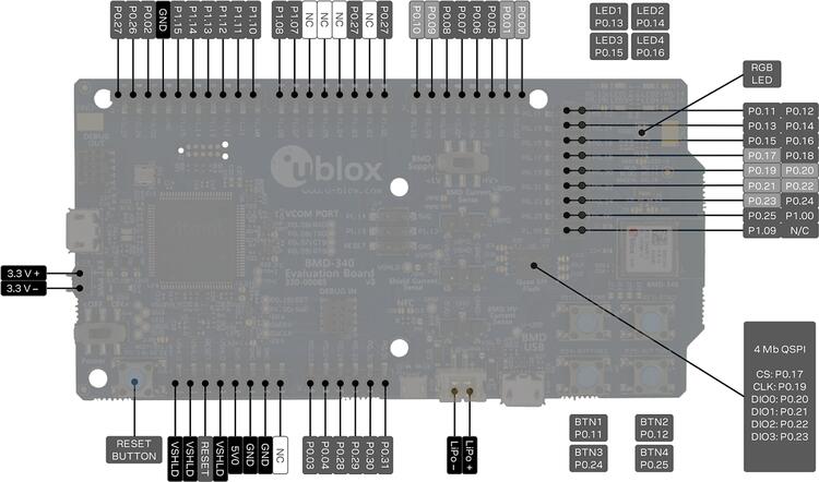
Connections and IOs
LED
LED1 (red) = P0.13
LED2 (red) = P0.14
LED3 (green) = P0.15
LED4 (green) = P0.16
D5 (red) = OB LED 1
D6 (green) = OB LED 2
External Connectors
Note
The pin numbers noted below are referenced to the pin 1 markings on the BMD-340-EVAL or BMD-341-EVAL for each header
J-Link Prog Connector (J2)
PIN # |
Signal Name |
|---|---|
1 |
VDD |
2 |
IMCU_TMSS |
3 |
GND |
4 |
IMCU_TCKS |
5 |
V5V |
6 |
IMCU_TDOS |
7 |
Cut off |
8 |
IMCU_TDIS |
9 |
Cut off |
10 |
IMCU_RESET |
Debug OUT (J3)
PIN # |
Signal Name |
|---|---|
1 |
EXT_VTG |
2 |
EXT_SWDIO |
3 |
GND |
4 |
EXT_SWDCLK |
5 |
GND |
6 |
EXT_SWO |
7 |
N/C |
8 |
N/C |
9 |
EXT_GND_DETECT |
10 |
EXT_RESET |
Debug IN (J26)
PIN # |
Signal Name |
|---|---|
1 |
BMD-340_VCC |
2 |
BMD-340_SWDIO |
3 |
GND |
4 |
BMD-340_SWDCLK |
5 |
GND |
6 |
BMD-340_SWO |
7 |
N/C |
8 |
N/C |
9 |
GND |
10 |
BMD-340_RESET |
Auxiliary (J9)
PIN # |
Signal Name |
|---|---|
1 |
P0.10 / NFC2 |
2 |
P0.09 / NFC1 |
3 |
P0.08 |
4 |
P0.07 |
5 |
P0.06 |
6 |
P0.05 / AIN3 |
7 |
P0.01 / XL2 |
8 |
P0.00 / XL1 |
Auxiliary (J10)
PIN # |
Signal Name |
|---|---|
1 |
P0.11 / TRACED[2] |
2 |
P0.12 / TRACED[1] |
3 |
P0.13 |
4 |
P0.14 |
5 |
P0.15 |
6 |
P0.16 |
7 |
P0.17 / QSPI_CS |
8 |
P0.18 / RESET |
9 |
P0.19 / QSPI_CLK |
10 |
P0.20 / QSPI_D0 |
11 |
P0.21 / QSPI_D1 |
12 |
P0.22 / QSPI_D2 |
13 |
P0.23 / QSPI_D3 |
14 |
P0.24 |
15 |
P0.25 |
16 |
P1.00 / TRACED[0] |
17 |
P1.09 / TRACED[3] |
18 |
No connection |
Arduino Headers
Power (J5)
PIN # |
Signal Name |
BMD-34x Functions |
|---|---|---|
1 |
VSHLD |
N/A |
2 |
VSHLD |
N/A |
3 |
RESET |
P0.18 / RESET |
4 |
VSHLD |
N/A |
5 |
V5V |
N/A |
6 |
GND |
N/A |
7 |
GND |
N/A |
8 |
N/C |
N/A |
Analog in (J8)
PIN # |
Signal Name |
BMD-34x Functions |
|---|---|---|
1 |
A0 |
P0.03 / AIN1 |
2 |
A1 |
P0.04 / AIN2 |
3 |
A2 |
P0.28 / AIN4 |
4 |
A3 |
P0.29 / AIN5 |
5 |
A4 |
P0.30 / AIN6 |
6 |
A5 |
P0.31 / AIN7 |
Digital I/O (J7)
PIN # |
Signal Name |
BMD-34x Functions |
|---|---|---|
1 |
D7 |
P1.08 |
2 |
D6 |
P1.07 |
3 |
D5 |
P1.06 |
4 |
D4 |
P1.05 |
5 |
D3 |
P1.04 |
6 |
D2 |
P1.03 |
7 |
D1 (TX) |
P1.02 |
8 |
D0 (RX) |
P1.01 |
Digital I/O (J6)
PIN # |
Signal Name |
BMD-34x Functions |
|---|---|---|
1 |
SCL |
P0.27 |
2 |
SDA |
P0.26 |
3 |
AREF |
P0.02 / AIN0 |
4 |
GND |
N/A |
5 |
D13 (SCK) |
P1.15 |
6 |
D12 (MISO) |
P1.14 |
7 |
D11 (MOSI) |
P1.13 |
8 |
D10 (SS) |
P1.12 |
9 |
D9 |
P1.11 |
10 |
D8 |
P1.10 |
J11
PIN # |
Signal Name |
BMD-34x Functions |
|---|---|---|
1 |
D12 (MISO) |
P0.14 |
2 |
V5V |
N/A |
3 |
D13 (SCK) |
P0.15 |
4 |
D11 (MOSI) |
P0.13 |
5 |
RESET |
N/A |
6 |
N/A |
N/A |
Programming and Debugging
Applications for the BMD-340-EVAL and BMD-341-EVAL board configurations can be built and flashed in the usual way (see Building an Application and Run an Application for more details); however, the standard debugging targets are not currently available.
Flashing
Follow the instructions in the Nordic nRF5x Segger J-Link page to install and configure all the necessary software. Further information can be found in Flashing. Then build and flash applications as usual (see Building an Application and Run an Application for more details).
Here is an example for the Hello World application.
First, run your favorite terminal program to listen for output.
$ minicom -D <tty_device> -b 115200
Replace <tty_device> with the port where the BMD-340-EVAL
or BMD-341-EVAL can be found. For example, under Linux,
/dev/ttyACM0.
Then build and flash the application in the usual way.
# From the root of the zephyr repository
west build -b ubx_bmd340eval/nrf52840 samples/hello_world
west flash
Debugging
Refer to the Nordic nRF5x Segger J-Link page to learn about debugging u-blox boards with a Segger J-LINK-OB IC.
Using UART1
The following approach can be used when an application needs to use more than one UART for connecting peripheral devices:
Add device tree overlay file to the main directory of your application:
&pinctrl {
   uart1_default: uart1_default {
      group1 {
         psels = <NRF_PSEL(UART_TX, 0, 14)>,
                 <NRF_PSEL(UART_RX, 0, 16)>;
      };
   };
   /* required if CONFIG_PM_DEVICE=y */
   uart1_sleep: uart1_sleep {
      group1 {
         psels = <NRF_PSEL(UART_TX, 0, 14)>,
                 <NRF_PSEL(UART_RX, 0, 16)>;
         low-power-enable;
      };
   };
};

&uart1 {
  compatible = "nordic,nrf-uarte";
  current-speed = <115200>;
  status = "okay";
  pinctrl-0 = <&uart1_default>;
  pinctrl-1 = <&uart1_sleep>;
  pinctrl-names = "default", "sleep";
};
In the overlay file above, pin P0.16 is used for RX and P0.14 is used for TX
Use the UART1 as
DEVICE_DT_GET(DT_NODELABEL(uart1))
Overlay file naming
The file has to be named <board>.overlay and placed in the app
main directory to be picked up automatically by the device tree
compiler.
Selecting the pins
Pins can be configured in the board pinctrl file. To see the available mappings, open the data sheet for the BMD-340 at the u-blox website [1], Section 2 ‘Pin definition’. In the table 3 select the pins marked ‘GPIO’. Note that pins marked as ‘Standard drive, low frequency I/O only (<10 kH’ can only be used in under-10KHz applications. They are not suitable for 115200 speed of UART.