Adafruit MCP4728 Quad DAC Shield
Overview
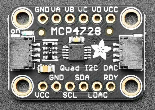
The Adafruit MCP4728 Quad DAC Shield features a Microchip 12-Bit Quad Output DAC and two STEMMA QT connectors. It has four output channels and an internal voltage reference.
Requirements
This shield can be used with boards which provide an I2C connector, for
example STEMMA QT or Qwiic connectors.
The target board must define a zephyr_i2c node label.
See Shields for more details.
Pin Assignments
Shield Pin |
Function |
|---|---|
SCL |
MCP4728 I2C SCL |
SDA |
MCP4728 I2C SDA |
LDAC |
MCP4728 load DAC input |
RDY |
MCP4728 ready. Low when busy with EEPROM write. |
VA - VD |
MCP4728 output channels |
When using this shield via the STEMMA QT connector, the supply voltage is 3.3 Volt, so the maximum internal voltage reference that can be used is 2.048 Volt.
The LDAC pin is pulled down on the shield, forcing an updated output voltage as soon as the input register has been written.
See microchip,mcp4728 for documentation on how to adjust the
devicetree file, for example to adjust the voltage reference, gain or power-down mode.
Programming
Set --shield adafruit_mcp4728 when you invoke west build. For example
when running the Digital-to-Analog Converter (DAC) sample:
# From the root of the zephyr repository
west build -b adafruit_feather_adalogger_rp2040 --shield adafruit_mcp4728 samples/drivers/dac
west flash
Connect a voltmeter to the shield output VA and observe how the voltage changes.
To run the sample for another output channel, modify the value for the dac-channel-id
attribute in the .overlay file for this shield.