Nucleo F030R8
Overview
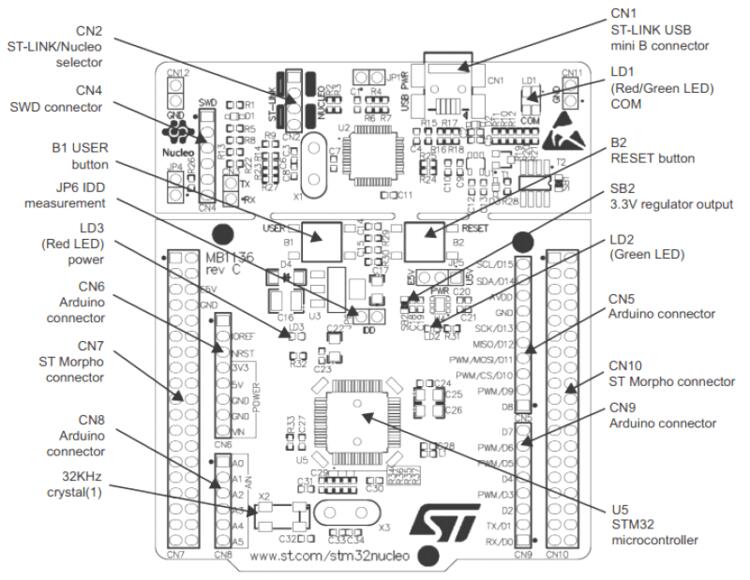
The STM32 Nucleo-64 development board with STM32F030R8 MCU, supports Arduino and ST morpho connectivity.
The STM32 Nucleo board provides an affordable, and flexible way for users to try out new concepts, and build prototypes with the STM32 microcontroller, choosing from the various combinations of performance, power consumption and features.
The Arduino* Uno V3 connectivity support and the ST morpho headers allow easy functionality expansion of the STM32 Nucleo open development platform with a wide choice of specialized shields.
The STM32 Nucleo board integrates the ST-LINK/V2-1 debugger and programmer.
The STM32 Nucleo board comes with the STM32 comprehensive software HAL library together with various packaged software examples.
More information about the board can be found at the Nucleo F030R8 website [1].
Hardware
Nucleo F030R8 provides the following hardware components:
STM32 microcontroller in QFP64 package
Two types of extension resources:
Arduino* Uno V3 connectivity
ST morpho extension pin headers for full access to all STM32 I/Os
On-board ST-LINK/V2-1 debugger/programmer with SWD connector:
Selection-mode switch to use the kit as a standalone ST-LINK/V2-1
Flexible board power supply:
USB VBUS or external source (3.3V, 5V, 7 - 12V)
Power management access point
Three LEDs:
USB communication (LD1), user LED (LD2), power LED (LD3)
Two push-buttons: USER and RESET
USB re-enumeration capability. Three different interfaces supported on USB:
Virtual COM port
Mass storage
Debug port
More information about STM32F030R8 can be found here:
Supported Features
The nucleo_f030r8 board supports the hardware features listed below.
- on-chip / on-board
- Feature integrated in the SoC / present on the board.
- 2 / 2
-
Number of instances that are enabled / disabled.
Click on the label to see the first instance of this feature in the board/SoC DTS files. -
vnd,foo -
Compatible string for the Devicetree binding matching the feature.
Click on the link to view the binding documentation.
nucleo_f030r8@1/stm32f030x8 target
On-target memory for this board target: 8 KiB of RAM, 64 KiB of Flash.
Type |
Location |
Description |
Compatible |
|---|---|---|---|
CPU |
on-chip |
ARM Cortex-M0 CPU1 |
|
ADC |
on-chip |
STM32 ADC1 |
|
Clock control |
on-chip |
STM32F0/G0 RCC (Reset and Clock controller)1 |
|
on-chip |
STM32 HSE Clock1 |
||
on-chip |
|||
on-chip |
STM32 LSE Clock1 |
||
on-chip |
STM32F0/F3 Main PLL1 |
||
Counter |
on-chip |
STM32 counters7 |
|
DMA |
on-chip |
STM32 DMA controller (V2bis) for the stm32F0, stm32F1 and stm32L1 soc families1 |
|
Flash controller |
on-chip |
STM32 Family flash controller1 |
|
GPIO & Headers |
on-chip |
||
on-board |
GPIO pins exposed on Arduino Uno (R3) headers1 |
||
on-board |
GPIO pins exposed on ST Morpho connector1 |
||
I2C |
on-chip |
STM32 I2C V2 controller2 |
|
Input |
on-chip |
STM32 Tocuh Sensing Controller (TSC) driver1 |
|
on-board |
Group of GPIO-bound input keys1 |
||
Interrupt controller |
on-chip |
ARMv6-M NVIC (Nested Vectored Interrupt Controller) controller1 |
|
on-chip |
STM32 External Interrupt Controller1 |
||
LED |
on-board |
Group of GPIO-controlled LEDs1 |
|
MTD |
on-chip |
STM32 flash memory1 |
|
NVMEM |
on-chip |
Fixed layout for Non-Volatile memory1 |
|
OTP memory |
on-chip |
STM32 embedded NVM OTP1 |
|
Pin control |
on-chip |
STM32 Pin controller1 |
|
PWM |
on-chip |
STM32 PWM6 |
|
Reset controller |
on-chip |
STM32 Reset and Clock Control (RCC) Controller1 |
|
RTC |
on-chip |
STM32 RTC1 |
|
Sensors |
on-chip |
STM32 VREF+1 |
|
on-chip |
STM32 TEMP for production calibrated sensors with a single calibration temperature1 |
||
Serial controller |
on-chip |
STM32 USART2 |
|
SMbus |
on-chip |
STM32 SMBus controller2 |
|
SPI |
on-chip |
STM32 SPI controller with embedded Rx and Tx FIFOs2 |
|
Timer |
on-chip |
ARMv6-M System Tick1 |
|
on-chip |
STM32 timers7 |
||
Watchdog |
on-chip |
STM32 watchdog1 |
|
on-chip |
STM32 system window watchdog1 |
nucleo_f030r8@2/stm32f030x8 target
On-target memory for this board target: 8 KiB of RAM, 64 KiB of Flash.
Type |
Location |
Description |
Compatible |
|---|---|---|---|
CPU |
on-chip |
ARM Cortex-M0 CPU1 |
|
ADC |
on-chip |
STM32 ADC1 |
|
Clock control |
on-chip |
STM32F0/G0 RCC (Reset and Clock controller)1 |
|
on-chip |
STM32 HSE Clock1 |
||
on-chip |
Generic fixed-rate clock provider3 |
||
on-chip |
STM32 LSE Clock1 |
||
on-chip |
STM32F0/F3 Main PLL1 |
||
Counter |
on-chip |
STM32 counters7 |
|
DMA |
on-chip |
STM32 DMA controller (V2bis) for the stm32F0, stm32F1 and stm32L1 soc families1 |
|
Flash controller |
on-chip |
STM32 Family flash controller1 |
|
GPIO & Headers |
on-chip |
||
on-board |
GPIO pins exposed on Arduino Uno (R3) headers1 |
||
on-board |
GPIO pins exposed on ST Morpho connector1 |
||
I2C |
on-chip |
STM32 I2C V2 controller2 |
|
Input |
on-chip |
STM32 Tocuh Sensing Controller (TSC) driver1 |
|
on-board |
Group of GPIO-bound input keys1 |
||
Interrupt controller |
on-chip |
ARMv6-M NVIC (Nested Vectored Interrupt Controller) controller1 |
|
on-chip |
STM32 External Interrupt Controller1 |
||
LED |
on-board |
Group of GPIO-controlled LEDs1 |
|
MTD |
on-chip |
STM32 flash memory1 |
|
NVMEM |
on-chip |
Fixed layout for Non-Volatile memory1 |
|
OTP memory |
on-chip |
STM32 embedded NVM OTP1 |
|
Pin control |
on-chip |
STM32 Pin controller1 |
|
PWM |
on-chip |
STM32 PWM6 |
|
Reset controller |
on-chip |
STM32 Reset and Clock Control (RCC) Controller1 |
|
RTC |
on-chip |
STM32 RTC1 |
|
Sensors |
on-chip |
STM32 VREF+1 |
|
on-chip |
STM32 TEMP for production calibrated sensors with a single calibration temperature1 |
||
Serial controller |
on-chip |
STM32 USART2 |
|
SMbus |
on-chip |
STM32 SMBus controller2 |
|
SPI |
on-chip |
STM32 SPI controller with embedded Rx and Tx FIFOs2 |
|
Timer |
on-chip |
ARMv6-M System Tick1 |
|
on-chip |
STM32 timers7 |
||
Watchdog |
on-chip |
STM32 watchdog1 |
|
on-chip |
STM32 system window watchdog1 |
Connections and IOs
Each of the GPIO pins can be configured by software as output (push-pull or open-drain), as input (with or without pull-up or pull-down), or as peripheral alternate function. Most of the GPIO pins are shared with digital or analog alternate functions. All GPIOs are high current capable except for analog inputs.
Board connectors:
Default Zephyr Peripheral Mapping:
UART_1 TX/RX : PA9/PA10
UART_2 TX/RX : PA2/PA3 (ST-Link Virtual COM Port)
I2C1 SCL/SDA : PB8/PB9 (Arduino I2C)
I2C2 SCL/SDA : PB10/PB11
SPI1 NSS/SCK/MISO/MOSI : PB6/PA5/PA6/PA7 (Arduino SPI)
SPI2 NSS/SCK/MISO/MOSI : PB12/PB13/PB14/PB15
USER_PB : PC13
LD1 : PA5
ADC : PA0
For more details please refer to STM32 Nucleo-64 board User Manual [4].
Programming and Debugging
The nucleo_f030r8 board supports the runners and associated west commands listed below.
| flash | debug | rtt | attach | reset | debugserver | |
|---|---|---|---|---|---|---|
| jlink | ✅ | ✅ | ✅ | ✅ | ✅ | ✅ |
| openocd | ✅ | ✅ (default) | ✅ | ✅ | ✅ | |
| probe-rs | ✅ | ✅ | ✅ | ✅ | ||
| stm32cubeprogrammer | ✅ (default) |
Nucleo F030R8 board includes an ST-LINK/V2-1 embedded debug tool interface.
Applications for the nucleo_f030r8 board configuration can be built and
flashed in the usual way (see Building an Application and
Run an Application for more details).
Flashing
The board is configured to be flashed using west STM32CubeProgrammer [5] runner, so its installation is required.
Alternatively, OpenOCD, JLink, probe-rs can also be used to flash the board using
the --runner (or -r) option:
$ west flash --runner openocd
$ west flash --runner jlink
$ west flash --runner probe-rs
Flashing an application to Nucleo F030R8
Here is an example for the Blinky application.
# From the root of the zephyr repository
west build -b nucleo_f030r8 samples/basic/blinky
west flash
You will see the LED blinking every second.
If using the C-01 board, select revision ‘1’ that supports the board.
# From the root of the zephyr repository
west build -b nucleo_f030r8@1 samples/basic/blinky
west flash
Debugging
You can debug an application in the usual way. Here is an example for the Blinky application.
# From the root of the zephyr repository
west build -b nucleo_f030r8 samples/basic/blinky
west debug
Again you have to use the adapted command for C-01.
# From the root of the zephyr repository
west build -b nucleo_f030r8@1 samples/basic/blinky
west debug
Board Revisions
Nucleo F030R8 has some version of board variants. STM32 Nucleo-64 board User Manual [4] mentions to Nucleo board variants.
The board version MB1136 C-01 or MB1136 C-02 is mentioned on the sticker, placed on the bottom side of the PCB.The board marking MB1136 C-01 corresponds to a board, configured as HSE not used.The board marking MB1136 C-02 (or higher) corresponds to a board, configured to use ST-LINK MCO as the clock input.
Using revision 2 adapted for C-02(or higher) as default when not explicitly selecting revisions. If using the C-01 board, select revision 1. Please see Flashing section.