STM3210C Evaluation
Overview
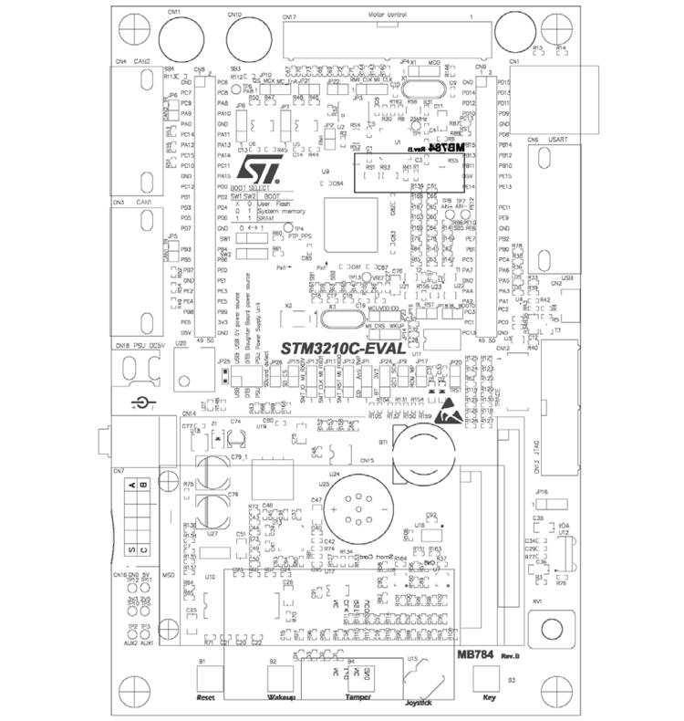
The STM3210C-EVAL evaluation board is a complete development platform for STMicroelectronic’s ARM Cortex-M3 core-based STM32F107VCT microcontroller.
The range of hardware features on the board help you to evaluate all peripherals (USB-OTG FS, ethernet, motor control, CAN, microSD CardTM, smartcard, USART, audio DAC, MEMS, EEPROM and more) and develop your own applications.
Extension headers make it easy to connect a daughterboard or wrapping board for your specific application.
More information about the board can be found at the STM3210C-EVAL website [1].
Hardware
STM3210C-EVAL provides the following hardware components:
Three 5 V power supply options
Power jack
USB connector
Daughterboard
Boot from user Flash, system memory or SRAM.
I2S audio DAC, stereo audio jack.
2 GByte (or more) microSD CardTM.
Both type A and B smartcard support.
I2C compatible serial interface 64 Kbit EEPROM, MEMS and I/O expander.
RS-232 communication.
IrDA transceiver.
USB-OTG full speed, USB microAB connector.
IEEE-802.3-2002 compliant ethernet connector.
Two channels of CAN2.0A/B compliant connection.
Inductor motor control connector.
JTAG and trace debug support.
3.2” 240x320 TFT color LCD with touch screen.
Joystick with 4-direction control and selector.
Reset, Wakeup, Tamper and User button.
4 color LEDs.
RTC with backup battery.
MCU consumption measurement circuit.
Extension connector for daughterboard or wrapping board.
More information about STM32F107VCT can be found here:
Supported Features
The stm3210c_eval board supports the hardware features listed below.
- on-chip / on-board
- Feature integrated in the SoC / present on the board.
- 2 / 2
-
Number of instances that are enabled / disabled.
Click on the label to see the first instance of this feature in the board/SoC DTS files. -
vnd,foo -
Compatible string for the Devicetree binding matching the feature.
Click on the link to view the binding documentation.
stm3210c_eval/stm32f107xc target
On-target memory for this board target: 64 KiB of RAM, 256 KiB of Flash.
Type |
Location |
Description |
Compatible |
|---|---|---|---|
CPU |
on-chip |
ARM Cortex-M3 CPU1 |
|
ADC |
on-chip |
STM32F1 ADC1 |
|
CAN |
on-chip |
STM32 CAN controller2 |
|
Clock control |
on-chip |
STM32 RCC (Reset and Clock controller)1 |
|
on-chip |
STM32 HSE Clock1 |
||
on-chip |
Generic fixed-rate clock provider3 |
||
on-chip |
STM32F105/F107 Main PLL1 |
||
on-chip |
STM32F105/F107 PLL21 |
||
on-chip |
STM32F1 Microcontroller Clock Output (MCO)1 |
||
Counter |
on-chip |
STM32 counters7 |
|
DAC |
on-chip |
STM32 family DAC1 |
|
DMA |
on-chip |
STM32 DMA controller (V2bis) for the stm32F0, stm32F1 and stm32L1 soc families2 |
|
Ethernet |
on-chip |
ST STM32 Ethernet MAC, a child node of the Ethernet controller1 |
|
on-chip |
STM32 MDIO Controller1 |
||
Flash controller |
on-chip |
STM32 Family flash controller1 |
|
GPIO & Headers |
on-chip |
STM32 GPIO Controller5 |
|
I2C |
on-chip |
STM32 I2C V1 controller2 |
|
Input |
on-board |
Group of GPIO-bound input keys1 |
|
Interrupt controller |
on-chip |
ARMv7-M NVIC (Nested Vectored Interrupt Controller)1 |
|
on-chip |
STM32 External Interrupt Controller1 |
||
LED |
on-board |
Group of GPIO-controlled LEDs1 |
|
MTD |
on-chip |
STM32 flash memory1 |
|
PHY |
on-chip |
This binding is to be used by all the usb transceivers which are built-in with USB IP1 |
|
Pin control |
on-chip |
STM32F1 Pin controller1 |
|
Power management |
on-chip |
STM32 power controller1 |
|
PWM |
on-chip |
STM32 PWM5 |
|
Reset controller |
on-chip |
STM32 Reset and Clock Control (RCC) Controller1 |
|
RTC |
on-chip |
STM32 RTC1 |
|
Sensors |
on-chip |
STM32 quadrature decoder5 |
|
on-chip |
STM32 Internal Temperature Sensor1 |
||
Serial controller |
on-chip |
||
on-chip |
STM32 UART2 |
||
SMbus |
on-chip |
STM32 SMBus controller2 |
|
SPI |
on-chip |
STM32 SPI controller3 |
|
Timer |
on-chip |
ARMv7-M System Tick1 |
|
on-chip |
STM32 timers7 |
||
USB |
on-chip |
STM32 OTGFS controller1 |
|
Watchdog |
on-chip |
STM32 watchdog1 |
|
on-chip |
STM32 system window watchdog1 |
Connections and IOs
Each of the GPIO pins can be configured by software as output (push-pull or open-drain), as input (with or without pull-up or pull-down), or as peripheral alternate function. Most of the GPIO pins are shared with digital or analog alternate functions. All GPIOs are high current capable except for analog inputs.
Board connectors:
Default Zephyr Peripheral Mapping:
UART_2_TX : PD5
UART_2_RX : PD6
USER_PB : PB9
LED2 : PD13
Programming and Debugging
The stm3210c_eval board supports the runners and associated west commands listed below.
| flash | debug | attach | rtt | debugserver | reset | |
|---|---|---|---|---|---|---|
| jlink | ✅ | ✅ | ✅ | ✅ | ✅ | ✅ |
| openocd | ✅ (default) | ✅ (default) | ✅ | ✅ | ✅ |
Flashing
STM3210C-EVAL board includes an ST-LINK/V2-1 embedded debug tool interface. At power-on, the board is in firmware-upgrade mode (also called DFU for “Device Firmware Upgrade”), allowing the firmware to be updated through the USB. This interface is supported by the openocd version included in Zephyr SDK.
Applications for the stm3210c_eval board configuration can be built and
flashed in the usual way (see Building an Application and
Run an Application for more details).
Flashing an application to STM3210C-EVAL
Connect the STM3210C-EVAL to your host computer using the USB port, then build and flash an application in the usual way.
Here is an example for the Blinky application.
# From the root of the zephyr repository
west build -b stm3210c_eval samples/basic/blinky
west flash
You will see the LED blinking every second.
Debugging
You can run a serial host program to connect with your STM3210C-EVAL board. For example, on Linux:
$ minicom -D /dev/ttyACM0
You can debug an application in the usual way. Here is an example for the Hello World application.
# From the root of the zephyr repository
west build -b stm3210c_eval samples/hello_world
west debug