Nucleo F446RE
Overview
The Nucleo F446RE board features an ARM Cortex-M4 based STM32F446RE MCU with a wide range of connectivity support and configurations. Here are some highlights of the Nucleo F446RE board:
STM32 microcontroller in QFP64 package
Two types of extension resources:
Arduino Uno V3 connectivity
ST morpho extension pin headers for full access to all STM32 I/Os
On-board ST-LINK/V2-1 debugger/programmer with SWD connector
Flexible board power supply:
USB VBUS or external source(3.3V, 5V, 7 - 12V)
Power management access point
Three LEDs: USB communication (LD1), user LED (LD2), power LED (LD3)
Two push-buttons: USER and RESET
More information about the board can be found at the Nucleo F446RE website.
Hardware
Nucleo F446RE provides the following hardware components:
STM32F446RET6 in LQFP64 package
ARM® 32-bit Cortex®-M4 CPU with FPU
Adaptive real-time accelerator (ART Accelerator)
180 MHz max CPU frequency
VDD from 1.7 V to 3.6 V
512 KB Flash
128 KB SRAM
10 General purpose timers
2 Advanced control timers
2 basic timers
SPI(4)
I2C(3)
USART(4)
UART(2)
USB OTG Full Speed and High Speed
CAN(2)
SAI(2)
SPDIF_Rx(1)
HDMI_CEC(1)
Quad SPI(1)
Camera Interface
GPIO(50) with external interrupt capability
12-bit ADC(3) with 16 channels
12-bit DAC with 2 channels
More information about STM32F446RE can be found here:
Supported Features
The nucleo_f446re board supports the hardware features listed below.
- on-chip / on-board
- Feature integrated in the SoC / present on the board.
- 2 / 2
-
Number of instances that are enabled / disabled.
Click on the label to see the first instance of this feature in the board/SoC DTS files. -
vnd,foo -
Compatible string for the Devicetree binding matching the feature.
Click on the link to view the binding documentation.
nucleo_f446re/stm32f446xx target
On-target memory for this board target: 128 KiB of RAM, 512 KiB of Flash.
Type |
Location |
Description |
Compatible |
|---|---|---|---|
CPU |
on-chip |
ARM Cortex-M4F CPU1 |
|
ADC |
on-chip |
STM32F4 ADC3 |
|
CAN |
on-chip |
STM32 CAN controller2 |
|
Clock control |
on-chip |
STM32F4 RCC (Reset and Clock controller)1 |
|
on-chip |
STM32 HSE Clock1 |
||
on-chip |
|||
on-chip |
|||
on-chip |
STM32 Clock multiplexer1 |
||
on-chip |
STM32 Microcontroller Clock Output (MCO)2 |
||
Counter |
on-chip |
STM32 counters8 |
|
DAC |
on-chip |
STM32 family DAC1 |
|
DMA |
on-chip |
STM32 DMA controller (V1)2 |
|
Flash controller |
on-chip |
STM32 Family flash controller1 |
|
GPIO & Headers |
on-chip |
STM32 GPIO Controller8 |
|
on-board |
GPIO pins exposed on Arduino Uno (R3) headers1 |
||
on-board |
GPIO pins exposed on ST Morpho connector1 |
||
I2C |
on-chip |
STM32 I2C V1 controller3 |
|
I2S |
on-chip |
STM32 I2S controller3 |
|
on-chip |
STM32 SAI Block controller1 |
||
Input |
on-board |
Group of GPIO-bound input keys1 |
|
Interrupt controller |
on-chip |
ARMv7-M NVIC (Nested Vectored Interrupt Controller)1 |
|
on-chip |
STM32 External Interrupt Controller1 |
||
LED |
on-board |
Group of GPIO-controlled LEDs1 |
|
on-board |
Group of PWM-controlled LEDs1 |
||
Memory controller |
on-chip |
STM32 Battery Backed RAM1 |
|
on-chip |
STM32 Flexible Memory Controller (FMC)1 |
||
on-chip |
STM32 Flexible Memory Controller (SDRAM controller)1 |
||
MMC |
on-chip |
STM32 SDMMC Host Controller1 |
|
MTD |
on-chip |
STM32F4 flash memory1 |
|
NVMEM |
on-chip |
Fixed layout for Non-Volatile memory1 |
|
OTP memory |
on-chip |
||
PHY |
on-chip |
This binding is to be used by all the usb transceivers which are built-in with USB IP2 |
|
Pin control |
on-chip |
STM32 Pin controller1 |
|
Power management |
on-chip |
STM32 power controller1 |
|
PWM |
on-chip |
||
Reset controller |
on-chip |
STM32 Reset and Clock Control (RCC) Controller1 |
|
RTC |
on-chip |
STM32 RTC1 |
|
Sensors |
on-chip |
STM32 quadrature decoder5 |
|
on-chip |
STM32 family TEMP node for production calibrated sensors with two calibration temperatures1 |
||
on-chip |
STM32 VREF+1 |
||
on-chip |
STM32 VBAT1 |
||
Serial controller |
on-chip |
||
on-chip |
STM32 UART2 |
||
SMbus |
on-chip |
STM32 SMBus controller3 |
|
SPI |
on-chip |
||
Timer |
on-chip |
ARMv7-M System Tick1 |
|
on-chip |
|||
USB |
on-chip |
STM32 OTGFS controller1 |
|
on-chip |
STM32 OTGHS controller1 |
||
Watchdog |
on-chip |
STM32 watchdog1 |
|
on-chip |
STM32 system window watchdog1 |
Connections and IOs
Nucleo F446RE Board has 8 GPIO controllers. These controllers are responsible for pin muxing, input/output, pull-up, etc.
Available pins:
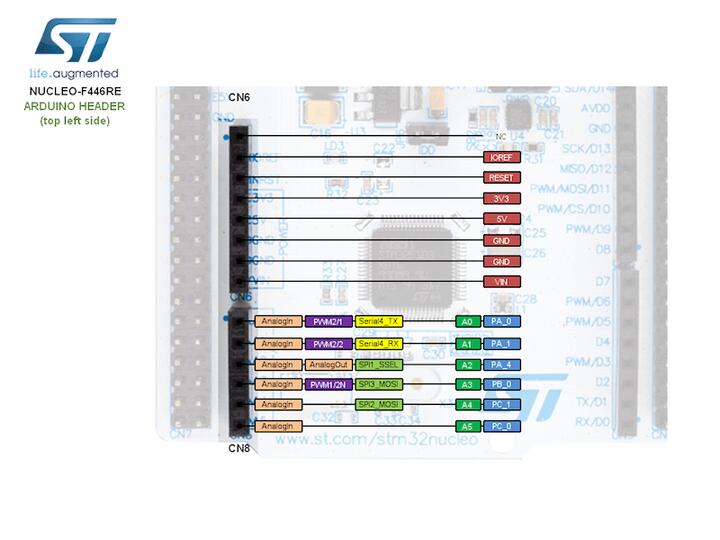
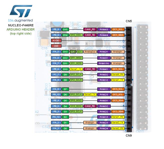
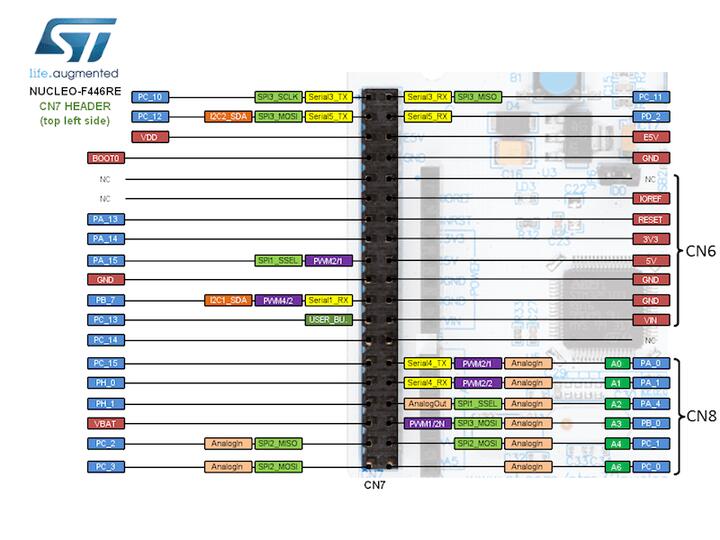
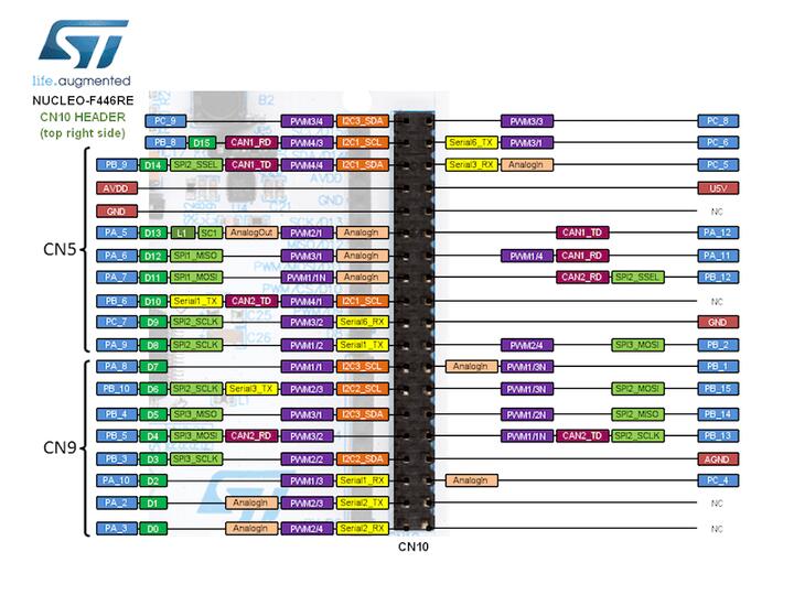
For more details please refer to STM32 Nucleo-64 board User Manual.
Default Zephyr Peripheral Mapping:
UART_1_TX : PB6
UART_1_RX : PB7
UART_2_TX : PA2
UART_2_RX : PA3
USER_PB : PC13
LD2 : PA5
I2C1_SDA : PB9
I2C1_SCL : PB8
I2C2_SDA : PB3
I2C2_SCL : PB10
I2C3_SDA : PB4
I2C3_SCL : PA8
System Clock
Nucleo F446RE System Clock could be driven by an internal or external oscillator, as well as the main PLL clock. By default, the System clock is driven by the PLL clock at 84MHz, driven by an 8MHz high-speed external clock.
Serial Port
Nucleo F446RE board has 2 UARTs and 4 USARTs. The Zephyr console output is assigned to UART2. Default settings are 115200 8N1.
Backup SRAM
In order to test backup SRAM you may want to disconnect VBAT from VDD. You can
do it by removing SB45 jumper on the back side of the board.
Controller Area Network
The TX/RX wires connected with D14/D15 of CN5 connector. Thus the board can be used with RS485 CAN Shield.
Programming and Debugging
The nucleo_f446re board supports the runners and associated west commands listed below.
| flash | debug | reset | rtt | debugserver | attach | |
|---|---|---|---|---|---|---|
| jlink | ✅ | ✅ | ✅ | ✅ | ✅ | ✅ |
| openocd | ✅ | ✅ (default) | ✅ | ✅ | ✅ | |
| stm32cubeprogrammer | ✅ (default) |
Nucleo F446RE board includes an ST-LINK/V2-1 embedded debug tool interface.
Applications for the nucleo_f446re board configuration can be built and
flashed in the usual way (see Building an Application and
Run an Application for more details).
Flashing
The board is configured to be flashed using west STM32CubeProgrammer runner, so its installation is required.
Alternatively, OpenOCD or JLink can also be used to flash the board using
the --runner (or -r) option:
$ west flash --runner openocd
$ west flash --runner jlink
Flashing an application to Nucleo F446RE
Here is an example for the Hello World application.
Run a serial host program to connect with your Nucleo board.
$ minicom -b 115200 -D /dev/ttyACM0
Build and flash the application:
# From the root of the zephyr repository
west build -b nucleo_f446re samples/hello_world
west flash
You should see the following message on the console:
$ Hello World! arm
Debugging
You can debug an application in the usual way. Here is an example for the Hello World application.
# From the root of the zephyr repository
west build -b nucleo_f446re samples/hello_world
west debug